|
|
|
|
|
|
|
|
|
|
|
Section 8.6.4.3
Beam Supporting Other Structural Element
Last Revised: 07/30/2011
A bearing plate designed to transfer loads between two structural elements follow the same principles as discussed in the prior section, however the limit state of bearing on concrete or masonry is not used.
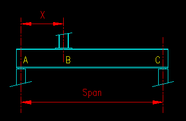
Figure 8.6.4.3.1 shows a common case of a column being supported by transfer beam. The location of load transfer that we are interested in is at point B on the beam.
Figure 8.6.4.3.1
Column Bearing on a Beam

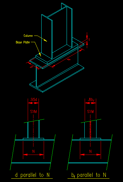
Figure 8.6.4.3.2 illustrates the connection of interest in an isometric view along with detail showing the critical dimensions for calculation in profile views.
Figure 8.6.4.3.1
Critical Dimensions

As was done in the previous section the bearing plate is modeled as a double cantilever beam, with the load distributed over the bottom where the plate contacts the supporting beam.
Determination of Length, N
The length of the plate, N is determined by the limit states of web local yielding and web crippling of the beam. These two limit states are presented in BGSCM 8.5.1 and BGSCM 8.5.2. Both limit states can be solved for a value of N.
N = min[req'd lb for web yielding, req'd lb for web crippling]
This distance can be shortened if bearing stiffeners are used on the beam web. The design of these plates is presented in BGSCM 8.6.5. The discussion here assumes that bearing stiffeners are not to be used.
Determination of Width, B
The width, B, is chosen to be wide enough to be attached to the column. Generally it is good to keep B as narrow as permitted but be at least as wide as the supported member.
Determination of Thickness, t
An equation for determination of thickness was previously developed. For this situation, the base plate is considered a double cantilever beam in one direction only. The dimension C in Figure 8.6.4.1 can be taken as shown in Figure 8.6.4.3.1 above, depending on the column orientation.
It should be noted that the values of .95d and .8bf used in Figure 8.6.4.3.1 for C are an extrapolation of the suggested values given on SCM pg 14-5 for a column base plate on concrete. To this point, I have not seen any research that would suggest any other values. These values appear to be theoretically conservative. Please send a correction in if you are aware of more precise research results.