|
|
|
|
|
|
|
|
|
|
|
Section 8.4.2
Deflection Limit State
Last Revised: 07/30/2011
In the absence of more specific criteria, criteria for structures with brittle finishes (as found in code documents for years) is frequently used. This simplistic criteria puts a limit of the span divided by 360 on the incremental deflection due to live (or transient) load only and a limit of the span divided by 240 on deflection under total load. These limit states are mathematic expressed as:
DLL < L/360
DTL < L/240
These limits were originally developed for members with "brittle" finishes, such as plaster. Plaster is not commonly used as a finishing material anymore. The goal of the limits was to minimize the possibility of damage to the finish and provide reasonable comfort for the building occupants. The criteria has persisted in practice.
Other criteria has been used that more explicitly addresses the use of the beam under consideration. For example, the Timber Construction Manual [ref. 12], page 66 suggests the values given in Table 8.4.2.1 and 8.4.2.2. Other references give different, but similar, criteria.
Table 8.4.2.1
AITC Recommended Deflection Limits
Used with Permission
|
Use Classification |
Applied Load Only | Applied Load + Dead Load |
| Roof Beams | ||
| - Industrial | L/180 | L/120 |
| - Commercial and institutional | ||
| - Without plaster ceiling | L/240 | L/180 |
| - With plaster ceiling | L/360 | L/240 |
| Floor Beams | ||
| - Ordinary usagea | L/360 | L/240 |
| Highway bridge stringers | L/200 to L/300 | |
| Railway bridge stringers | L/300 to L/400 | |
| aOrdinary usage classification for floors is intended for construction in which walking comfort and minimized plaster cracking are the main considerations. These recommended deflection limits may not eliminate all objections to vibrations such as in long spans approaching the maximum limits or for some office and institutional applications where increased floor stiffness is desired. For these usages, the deflections limits of table 8.4.2.2 have been found to provide additional stiffness. | ||
Table 8.4.2.2
AITC Deflection Limits for Uses Where
Increased Floor Stiffness is Desired
Used with Permission
|
Use Classification |
Applied Load Only | Applied Load + Dead Loada |
| Floor Beams | ||
| - Commercial, Office & Institutional | ||
| - Floor Joists, spans to 26 ftb | ||
| - LL < 60 psf | L/480 | L/360 |
| - 60 psf < LL < 80 psf | L/480 | L/360 |
| - LL > 80 psf | L/420 | L/300 |
| - Girders, spans to 36 ftb | ||
| - LL < 60 psf | L/480 | L/360 |
| - 60 psf < LL < 80 psf | L/420 | L/300 |
| - LL > 80 psf | L/360 | L/240 |
| aThe AITC includes
a modifier on DL depending on whether or not the timber is seasoned. bFor girder spans greater than 36 ft and joist spans greater than 26 ft, special design considerations may be required such as more restrictive deflection limits and vibration considerations that include the total mass of the floor. |
||
The span length, L, in the limit equations above is taken as the distance between center of supports. For cantilever beams, a value equal to twice the actual cantilever length is generally used for the L in determining the deflection limits.
Ponding
|
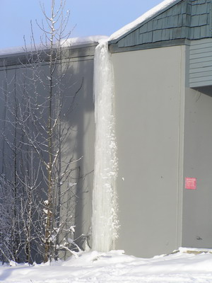
Figure 8.4.2.1 |
 |
In roof systems that are essentially flat, provisions must be made to support ponding water. Ponding is a progressive event. The more water on the roof, the more deflection you get, which means that even more water can be retained, which leads to more deflection, etc... If the beam is stiff enough, then ponding can be minimized.
The best solution to the ponding problem is architectural. It is strongly recommended that sufficient slope be given to roof systems (a minimum of 1/4" per foot) to prevent ponding. Appropriate drainage must also be provided.
Roofs in cold regions that use scuppers to drain a roof located behind a parapet may become plugged with ice, resulting in unintentional ponding, leading to disastrous results. Figure 8.4.2.1 shows such a frozen scupper. Scuppers must also be made large enough to allow water to escape during a deluge and to minimize blockage by debris.
Tolerances of Attached Elements or Non-Structural Elements Below
Often times, non-structural elements have specific deflection tolerances that are more restrictive than the general criteria given above. These tolerances generally are expressed in terms as a maximum deflection value and must be considered in design.
For example, a floor girder spanning 36 ft may deflect up to 1.2 inches under a live load only deflection limit of L/360. Any non-structural partition under the beam must be able to accommodate this deflection. However, if it cannot, then the amount of live load deflection that can be accommodated becomes the new deflection criteria for this beam.
Vibrations
Certain vibrations have been found to be objectionable in most occupancy classifications. Vibrations are often lumped together with deflection since both are stiffness related. Vibrations are a function of stiffness and mass. The frequency of the vibrations is of more concern than the amplitude. The treatment of vibrations is beyond the current scope of this text.
Selection of Criteria
The choice of deflection criteria is a project dependent. Other criteria may be encountered that have been developed for special structures and/or situations. These may be considered as needed.
For the problems in this text, the equations listed at the start of this section will be used unless otherwise specified.