|
|
|
|
|
|
|
|
|
|
|
Section 8.6.2
Cover Plates
Last Revised: 07/30/2011
|
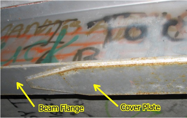
Figure 8.6.2.1 Beam with Cover Plates Click on image for larger view |
 |
|
Figure 8.6.2.2 |
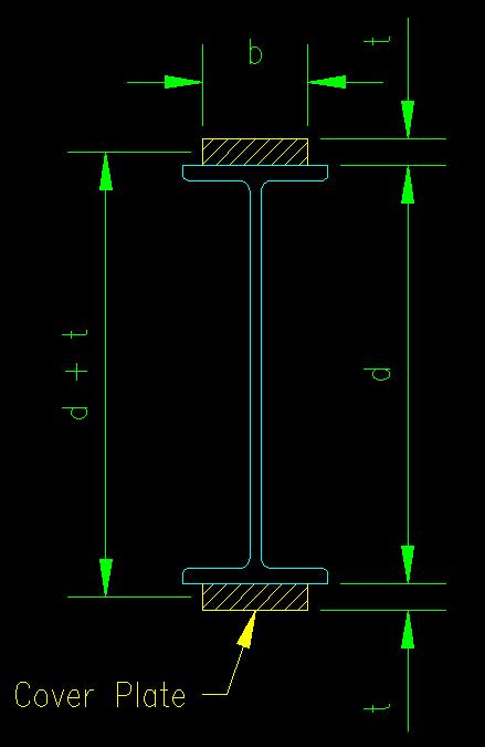 |
Cover plates are plates added to the flanges of beams to increase the flexural capacity of the beam over some portion of the beam. The use of cover plates in regions of high moment allows the use of a section of lesser weight and lesser flexural capacity to be used as the primary beam. This may result in a cost savings in some cases. Figure 8.6.2.1 shows a typical bridge beam with cover plates. Figure 8.6.2.2 shows a typical drawing of a W section with cover plates.
This technique is useful for compact beams that are not subject to the limit state of lateral torsional buckling (LTB). SCM F13.3 specifies many of the parameters associated with the design of cover plates.
Determining Size of Cover Plates
In the case of a compact beam not subject to LTB, the flexural limit state is stated as:
Req'd Mn = (Mu/f or MaW) < FyZtotal
Adding cover plates increases the Z of the section. For symmetrical cross sections with symmetrically applied plates, the design inequality becomes:
Req'd Mn < Fy (Zsection + Zplates)
For design purposes, this equation can be re-written as:
Zplates > (Req'd Mn / Fy) - Zsection
For symmetrical plates, Z is the area of one plate times the distance between the centers of the two plates, so the strength requirement for symmetrical cover plates becomes:
Zplates = bt (d+t) > (Req'd Mn / Fy) - Zsection
Where
- d is the overall depth of the steel section to which the cover plates are being added and
- t is the thickness of the cover plates.
For unsymmetrical plates (i.e. the cover plates are of different sizes or a cover plate is applied to only one flange), the Z for the whole section must be recomputed using basic concepts. This will involve finding the centriodal axis, locating the center of the areas above and below the centriodal axis, then finding Z by:
Ztotal = (Ag/2) (distance between the centroids of the two halves)
A restriction on the relative values of b and t is the requirement that the plate be compact. As the plate is generally connected to the flange with welds or bolts on both sides, the cover plated is considered a stiffened element and SCM Table B4.1 case 12 applies:
b/t < 1.12 sqrt(E/Fy)
As there are two design variables, b and t, there are an infinite number of combinations of the variables that will result in a Ztotal that matches Zreq'd. The best solution is generally the one that yields the smallest area, bt.
Determining the Length of Cover Plates
The cover plate must extend, at a minimum, over the distance where the moment demand exceeds the moment capacity provided by base section without the cover plates. Figure 8.6.2.3 illustrates this concept. In the example shown the moment capacity of the base section is sufficient near the ends of the member where the moment is low but needs to be enhanced where moment demand exceeds the capacity of the base section. The intersection of the moment demand and moment capacity curves can generally be determine mathematically since it is possible to write equations for both curves.
Figure 8.6.2.3
Cover Plate Length
Click on image for larger view

SCM F13.3 requires that the plates extend beyond the theoretical cutoff points but does not give any explicit requirement on how far. The section does, however, require that you provide a connection beyond the theoretical cutoff points which is capable of developing the full force computed for the plate. This connection can be made with either fillet welds or slip-critical bolts.
One reason for extending beyond the theoretical cutoff point is to account for uncertainty associated with the probabilities used in predicting the loads applied to the beam.
Another reason for extending the cover plates is to account for the presence of stress concentrations. It has been well established that at locations where there is a change in geometric stiffness there are larger stresses in the member than predicted by the basic mechanics stress equations. Consequently it is good to make this transition (from beam without cover plate to beam with cover plate), which is a change in geometric stiffness, where there is some reserve capacity in the member.
Connecting Cover Plates to Flanges
As mentioned above, SCM F13.3 requires a connection at the ends of each cover plate sufficient to "develop the cover plate's portion of the flexural strength in beam or girder at the theoretical cut off points." The commentary on this section states the force at the ends "can conservatively be taken as the full yield strength for LRFD or the full yield strength of the cover plate divided by 1.5 for ASD." Only slip-critical bolts or fillet welds can be used. The connections are designed using the principles covered in Chapters 4 and 5 of this text.
For fillet welds, SCM F13.3 does require a minimum length, a', beyond the theoretical cutoff point. The length, a' varies from one to two times the cover plate width, depending on the weld group configuration and weld size relative to plate thickness.
SCM F13.3 also requires connections to "be proportioned to resist the total horizontal shear resulting from the bending forces on the girder." Using the shear flow equation from mechanics, the force per unit length of plate, q, at any location along beam that must be transferred between the plate and beam is:
q = t b = (Req'd Vn) Q / I = (Req'd Vn) [bt((d+t)/2)] / I
Where Req'd Vn = Vu/f or VaW, depending of design philosophy being used.
Since Req'd Vn varies with position on the beam, q also varies along the length of the beam.
For welds, q is the required strength of the two fillet welds that would be applied along each side of the plate. The size will vary along the length of the beam. Once the required weld size drops below minimum size, the weld may be spaced intermittently.
For bolts (and intermittently spaced welds), the spacing is determined by
Req'd Rn = q s < (2 connectors) rn
s < 2 rn / q
Where rn = nominal shear strength of one weld segment or one bolt.
The function for required spacing, s, can be graphed along the length of the beam. The actual connector spacing at any given part of the beam will need to be less than what is required. Figure 8.6.2.4 shows such a graph. Note that fastener spacing is infinite where req'd Vn is zero (i.e. at mid-span in this case).
Figure 8.6.2.4
Fastener Spacing vs. Location
In practice ,some designers like to limit fastener spacing to no more than the width of the cover plate or flange, whichever is smaller.
A more analytical method (not found in the SCM) is to compute a maximum spacing based on buckling strength of the cover plate with the goal being to select a spacing that keeps the Euler buckling stress of the cover plate greater than Fy.
Fy < p2 E / (Le / r)2
Where:
- Le = 0.5 s (Assumes fixed ends, no joint translation)
- r = sqrt( I / A )
- I = bt3 / 12
- A = bt
Making the substitutions for I and A and solving for the spacing s:
s < p t sqrt( E / (3 Fy))
Any spacing, s, that meets this criteria will prevent buckling and control the spacing when the beam shear is low.
To summarize the fastener spacing requirement:
s < minimum [ 2 rn / q , p t sqrt( E / (3 Fy)) ]
<<< Previous Section <<< >>> Next Section >>>