|
|
|
|
|
|
|
|
|
|
|
Section 8.6.4.1
Beam Bearing on Concrete
Last Revised: 07/30/2011
A bearing plate takes the reaction of a steel beam and distributes that force over a larger area that is made of a material that is not as strong as steel. The action is essentially the same as a footing that distributes a large load to softer soil. The bearing plate is necessary to avoid crushing of the weaker material and to distribute the reaction force over a sufficient length of beam to prevent web yielding or crippling.
A bearing plate is generally a rectangular plate that can described by its dimensions as shown in Figure 8.6.4.1.1: width (N), length (B), and thickness (t).
Figure 8.6.4.1.1
Bearing Plate Concepts
Click on hotlinks in image to get larger
views
As previously discussed in BGSCM 8.6.4, the bearing plate is modeled as a double cantilever beam, with the load distributed over the bottom where the plate contacts the weaker material and a "point" reaction where the beam contacts the plate, distributed over a smaller area that is N wide and a distance "2k" wide.
Relating these variables to the general discussion found in section 8.6.4, the distances "B" and "N" are the same as previously defined, while "C" equals 2k, where "k" is the distance from the face of the beam flange to the toe of the fillet that connects the web with the flange. The value of k is tabulated in the AISC section property tables.
Determining the Width, N, of the Plate
The width of the plate, N, is dictated by web yielding, web crippling, or the available width on the supporting surface. When considering web yielding and web crippling, N is equivalent to the variable lb in the SCM J10 equations.
N = min[req'd lb for web yielding, req'd lb for web crippling, available width of supporting structure]
Typically a designer will first determine the required width, N, based on beam web yielding and web crippling then compare this against the available length for bearing on the supporting surface. If the supporting surface is not large enough then N is taken as the available width and bearing stiffeners are added to the beam.
Determining the Length, B, of the Plate
Once the width, N, has been determined the length, B, is determined so as to create a large enough area to lower the bearing stress to the point that the supporting surface will not experience crushing failure.
The limit state for bearing on concrete is found in SCM J8. The strength of the concrete bearing surface is a function of the plate contact area (NB). Since N is known, this limit state can be solved for B.
The Limit State of Bearing on Concrete
The basic limit state follows the standard form. The statement of the limit states and the associated reduction factor and factor of safety are given here:
| LRFD | ASD |
| Ru < fPp | Ra < Pp/W |
| Req'd Pp = Ru / f < Pp | Req'd Pp = Ru W < Pp |
| Ru / (fPp) < 1.00 | Ra / (Pp/W) < 1.00 |
| f = 0.65 | W = 2.31 |
The values of Ru and Ra are the LRFD and ASD factored loads, respectively, applied to the beam.
In this case Pp is the nominal bearing strength of the concrete surface is computed using SCM equations J8-1 and J8-2. In actuality, equation J8-1 is a special case of equation J8-2 (when A1 = A2), so equation J8-2 can be used at all times.
The allowable stress on the concrete is taken as 0.85f'c, where f'c is the 28-day compressive strength of a standard laboratory cured 6 in. diameter x 12 in. long test specimen of the concrete used for the bearing surface.
A1 is the actual contact area (NB) between the concrete and the steel plate. It has been observed that when A1 is surrounded by additional surface area that the concrete can take more stress. This is the result of the contacted concrete being contained. Consequently, the allowable bearing stress may be increased by the square root of the ratio of A2/A1 (up to a limit).
Figure 8.6.4.1.2 illustrates most of the physical dimensions associated with the computation of Pp.
Figure 8.6.4.1.2
Pp Parameters
Click on image to get larger view
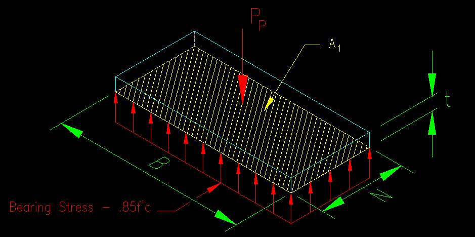
Figure 8.6.4.1.3 illustrates the computation of A2. A2 is defined as the "maximum area of the portion of the supporting surface that is geometrically similar to and concentric with the loaded area". The maximum area will always have one edge in common with the available concrete surface.
Figure 8.6.4.1.3
A2 Computation
Click on image to get larger view
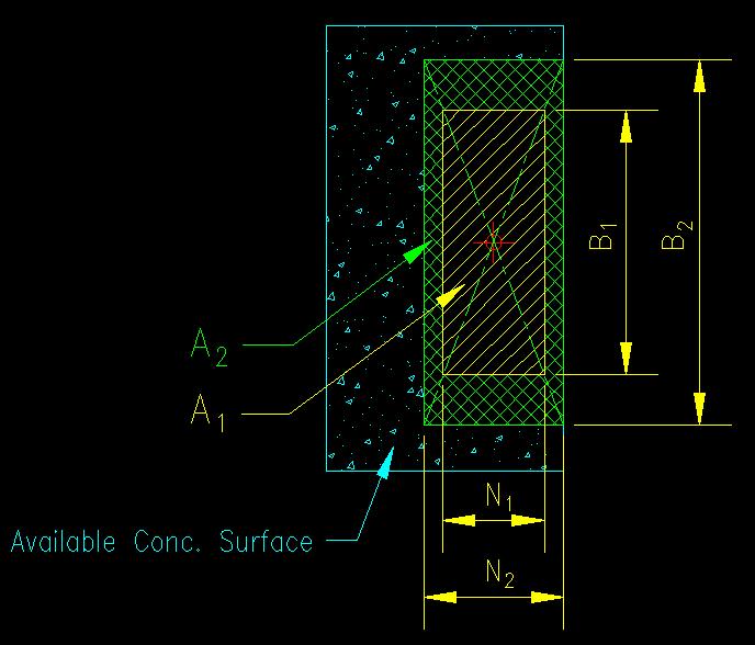
Geometrically similar means that (B1/N1) = (B2/N2). N2 can be determined by the distance to edge of the available concrete. This means that B2 = B1 (N2/N1). If B2 then overhangs the edge of the available concrete, then determine B2 by the distance to the edge of the available concrete and compute N2 = N1 (B2/B1). Depending on which is easier to obtain (N2 or B2) you can use one of the equations below to find the ratio of A2/A1 without knowing the other dimension:
A2/A1 = (N2B2) / (N1B1) = (N2 B1(N2/N1)) / (N1B1) = (N2/N1)2
or
A2/A1 = (N2B2) / (N1B1) = (N1(B2/B1) B2) / (N1B1) = (B2/B1)2
Typically, N2 is easier to determine than B2 since N2 is often limited by width of the concrete element in that direction. The resulting substitution for A2/A1 can then be substituted into the design inequality for the limit state of concrete bearing strength.
By writing the design inequality and having already selected the dimension N the dimension B can now be determined
Req'd Pp = (Ru/f or RaW) < min[0.85 f'c (B1N1) sqrt(A2/A1), 1.7 f'c (B1N1)]
or, if N2 is known
Req'd Pp < min[0.85 f'c (B1N1) (N2/N1), 1.7 f'c (B1N1)]
Req'd Pp < min[0.85 f'c (B1N2), 1.7 f'c (B1N1)]
Req'd Pp < f'c B1min[0.85 N2, 1.7 N1]
This equation can be solved directly for B1 which is the dimension B of the base plate.
B > Req'd Pp / (f'c min[0.85 N2, 1.7 N1])
Determining the Thickness, t, of the Plate
The last thing to specify is the thickness of the plate. This is done using the equation for thickness developed in BGSCM 8.6.4. Since the value of "C" equals 2k, the equation for thickness can be written as: