|
|
Section 5.8.4
Example Problem 5.4
Last Revised: 05/30/2023
The example problems presented in this section have a spreadsheet solution. You will need this file to follow along with the presented solutions. You can click on the following link to get the file:
Chapter 5: Excel Spreadsheet Solutions
Example Problem 5.4: This example implements both the elastic and IC methods for eccentric load in the plane of the faying surface. These problems are best done by spreadsheet, particularly the IC method which is iterative.
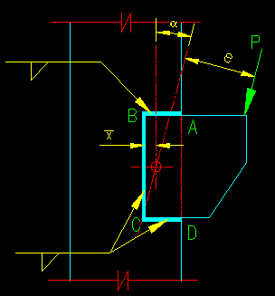
Given: The eccentrically loaded welded connection shown in Figure 5.8.4.1. The steel is A36 steel. The electrode is F6. The eccentricity, e, is 8 inches and the angle, a, is 10 degrees. The applied load consists of 10 kips dead load and 25 kips live load. Consider both LRFD and ASD.
Figure 5.8.4.1
In-Plane Eccentrically Loaded Connection
Click on image for larger view
Wanted:
a) Fillet weld size using the elastic vector method.
b) Fillet weld size using the IC method.
c) Fillet weld size using the AISC coefficient method.
Solution:
This problem can be done by hand but is very involved and would take up way too many pages due to the iterative nature of the IC method. Also, many of the calculations are best done in table form where the same equations are applied over and over again. Given these two situations, a spreadsheet is definitely a better way to go. That is what we have done here. You need to be looking at the spreadsheet as we discuss this problem.
As we are looking at both LRFD and ASD in this problem, you will notice that there are some parallel computations made.
The first part of the problem solution is focused on finding the required geometric quantities and the magnitudes of the applied load.
First, we need to locate the center of the weld group. All computations are made relative to the coordinate system that is centered on the weld group. The original reference system used for the centroid calculation is located at point C on the weld group.
Once we have the centroid, we then compute the critical point coordinates relative to the centriod of the weld group.
Now we are ready to look at method specific calculations. We begin with the elastic vector method.
Elastic Vector Method
In this case, we pick a particular weld size then compute the capacity of the connection to hold the applied loads.
To compute the stresses, we need to know the area of weld and the polar moment of inertia, Ip. While we can compute these for the selected weld size, we have chosen to do this for an effective throat thickness, te, of 1". The results can be scaled to the actual weld size without having to repeat the calculation every time you change weld size.
With the section properties we can now compute the translational and rotational stresses with basic mechanics expressions:
Translational stress = Translational Force / Area
Rotational Stress = (Torsion) * r / Ip
These stress components have direction so they are broken into their vertical and horizontal components so that they can be vectorially added.
Finally, the resultant stress is compared against the stress component of the weld strength computation. If there is insufficient or significant excess in capacity, then a new weld size is chosen, and the computations repeated until the best solution if found.
The IC Method
Just a quick look at the spreadsheet will show that the IC method is computationally more intensive than the elastic vector method. And just the size of the spreadsheet does not really begin to tell the story!
For this method, we have divided the weld into 1 inch segments. We then can find the element centroid coordinates relative to the weld group center of gravity and relative to the instantaneous center (IC) once it is chosen. We also need to know the orientation of each element so that we can later compute the angle of element force to element axis.
With the elementary geometric information we can then compute the various quantities as described in BGSCM 5.2.
One key to the process is to locate the IC. When the applied force is neither vertical nor horizontal, this process involves finding both the x and y coordinates of the IC. The search can be done manually or by using a multivariable search routine such as the "solver" available with Excel. The objective of the search is to find the IC location such that the equilibrium equations (at the end of the computation) all yield the same value of P.
Remember that the IC method simply finds the force, Pn, that would cause the worst loaded weld element to reach its capacity, rn. This value of Pn can be compared against the required Pn as produced by each of the design philosophies.
It this problem, we find that the IC method allows a substantially smaller weld than does the elastic vector method.
The AISC Coefficient Method
For this problem, there we need to interpolate twice to find the coefficient that meets our need. The spreadsheet shows this computation. See SCM pgs 8-95 and 8-96 for the formulas used to apply the resulting coefficient to our problem. The objective is to solve for the size of the weld with the given loads and coefficient.
