|
|
Section 5.4
Effective Areas of Base Metal
Last Revised: 07/08/2023
The capacity of a welded connection is limited by the lesser of the strength of the weld or the strength of the material that the weld is attached to (i.e., the base metal). The strength of the base metal is the force necessary to cause shear rupture or tensile yielding of the base metal where the weld is attached.
A key principle is that the area of rupture sees the full force that the weld sees.
For CJP welds the base metal effective areas are the same as those for the welds themselves. That is the thickness of the plate times the length of the weld.
For PJP welds the base metal effective areas are the same as for the CJP welds. That is, the effective area equals the plate thickness times the length of the weld.
For fillet, plug, and slot welds, the determination of effective base metal area gets more complicated.
The fillet, plug, and slot welds tend to transfer their forces via shear, so the predominate base metal failure is shear rupture. This is similar to the block shear limit state considered for tension member design.
Base Metal Effective Area Example 1
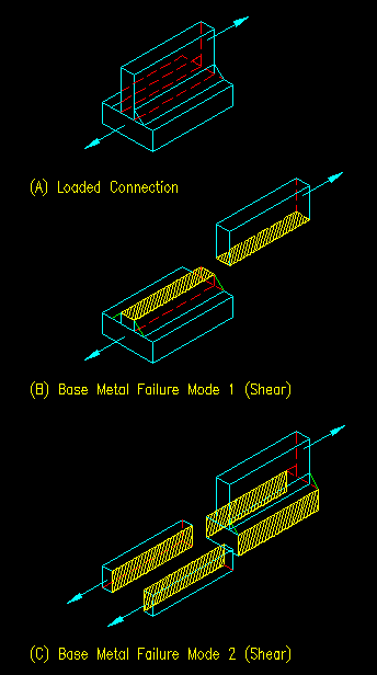
Figure 5.4.1(A) shows a T connection made with two fillet welds (one on each side of the stem). The connection is loaded with a shearing force as shown.
As is the case in all connections, there are two potential base metal failure modes to consider. One for each base metal being joined. The effective areas (i.e., the failure surfaces) are shown with a yellow hatch.
Figure 5.4.1(A)
Base Metal Effective Area Example #1
Click on hotlinks in image for larger views

Failure example 1 has an effective area equal to the thickness of the stem times the length of the weld. This failure surface supports the full shearing force. Also notice that this effective area "supports" two fillet welds. That is while the failure surface shown supports the full load, that load is transferred to two equal size fillet welds, each seeing half of the applied force. Consequently, to avoid base metal failure, the base metal strength must be TWICE that of each weld, or you could say to avoid weld failure, the welds must each be only half as strong as the base metal.
Failure mode 2 has two failure surfaces that, together, support the full shearing force. Another way to look at this, due to symmetry, is that each failure surface supports half the applied force. The effective area in each case equals the thickness of the plate times the length of the weld. In this mode, the effective area sees the same force that the attached weld does. To avoid base metal failure, the base metal needs to be as strong as the weld it is attached to and vice versa.
Note that every weld is connected to two base metals. In the case of example 1, each of the two welds share one shear area on the stem, but each has its own adjacent base metal shear area on the bottom plate.
Base Metal Effective Area Example 2
Figure 5.4.1(B) is the same connection as example 1 with the stem loaded in tension. Note that the bottom piece's effective areas are still in shear.
Figure 5.4.1(B)
Base Metal Effective Area Example #2
Click on hotlinks in image for larger views

In this example, we have the same effective areas (failure surfaces) as in the prior example only now the stem is in tension and the stress on the effective area is tensile. The stress on the bottom plate is still shear (though in a different direction).
Special Cases
There are two cases where the base metal strength of one of the connected parts is normally not computed because the base metal failure mode is always stronger than the weld.
Edge of a plate element (Base Metal Effective Area Example 3)
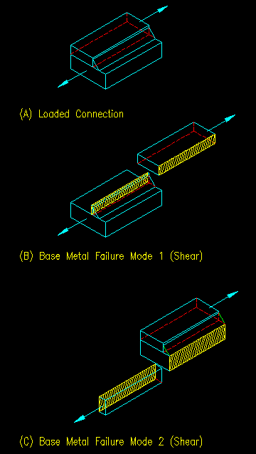
Figure 5.4.1(C) shows the base metal shear rupture areas for a typical fillet weld at the edge of a plate. Such a connection can occur in overlapping plates or at the edge of a flange from rolled shape or the edge of an angle leg.
Figure 5.4.1(C)
Base Metal Effective Area Example #3
Click on hotlinks in image for larger views

The effective areas for both modes are subjected to the same shearing force as the weld. In failure mode #2 it is possible, if the plate is thin enough, that the base metal of the lower plate will control the strength of the welded connection. For failure mode #1, however, the plate thickness is always at least equal to the leg size, "a", of the weld if not larger. This means that the plate thickness is always at least 40% (tpl > te/sin 45o) greater than the effective throat of the weld. As similar strength materials are used for the weld and base metal, this leads to the conclusion that the failure mode #1 will never control the welded connection design. Consequently, only base metal failure mode #2 would be considered when computing strength of the welded connection.
Note that the same analysis would be true for the case where the applied force is normal to the faying surface since both of the base metal failure surfaces would be still be subjected to the same shearing force as the weld. Similarly, if the applied force is in plane with the faying surface but orthogonal to the direction shown, the two effective areas would be in tension instead of shear, but the strength of the base metal in failure mode #1 would still be significantly stronger than the weld so the same conclusion can be reached. In any of the cases, the base metal strength of the plate connected along its edge will be stronger than the fillet weld and can be neglected in the computations.
Corner of a Member with Two Intersecting Plate Elements (Base Metal Effective Area Example 4)
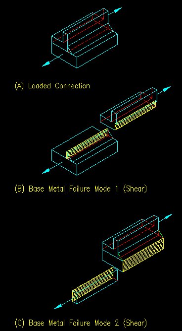
Figure 5.4.2 shows the base metal shear rupture areas for a typical fillet weld at the edge member that consists of two intersecting plate elements in the vicinity of the weld. Such a condition might occur where the member is a channel or angle being welded to a gusset plate. There would be other cases as well.
Figure 5.4.2
Base Metal Effective Area Example #4
Click on hotlinks in image for larger views

As with the edge of plate connection, the effective areas for both modes are subjected to the same shearing force as the weld. In failure mode #2 it is possible, if the plate is thin enough, that the base metal of the lower plate will control the strength of the welded connection. For failure mode #1, however, defining the failure path is somewhat difficult, but the thickness variable is at least equal to the leg size, "a", of the weld. This means that the base metal effective area is always 40% (tpath > te/sin 45o) greater than the effective throat of the weld. As similar strength materials are used for the weld and base metal, this leads to the conclusion that the failure mode #1 will never control the welded connection design. Consequently, only base metal failure mode #2 would be considered when computing strength of the welded connection.
Note that the same analysis would be true for the case where the applied force is normal to the faying surface since both of the base metal failure surfaces would be still be subjected to the same shearing force as the weld. Similarly, if the applied force is in plane with the faying surface but orthogonal to the direction shown, the two effective areas would be in tension instead of shear, but the strength of the base metal in failure mode #1 would still be significantly stronger than the weld so the same conclusion can be reached. In any of the cases, the base metal strength of the member with two intersecting plate elements will be stronger than the fillet weld and can be neglected in the computations.