|
|
Section 10.8.1
Example Problem 10.1
The solution for this example problem are found in the spreadsheet that can be obtained by clicking on the link below.
Download spreadsheet file: BGSCMC10ExProb.xlsm
Given: An interior floor beam as shown in Figure 10.8.1.1. The W16x26 beams are spaced 4'-0" O.C. and span 40 ft. The beams are simply supported. The 4" thick normal weight concrete slab has a 28-day compressive strength, f'c, of 3.5 ksi. The studs are 1/2" diameter and have Fu = 65 ksi. The floor live load is taken as 50 psf and the floor dead load (including beam, slab, and other items) is 75 psf.
Figure 10.8.1.1
Floor Section

Wanted: For a typical interior beam
- Compute Ma/(Mn / W),
- Determine the number and layout of studs required for full composite action,
- Determine the Live Load only deflection.
Solution:
Compute Ma/(Mn / W)
To compute the nominal moment capacity, Mn, we will need to determine the effective slab width, bE, and the location of the PNA.
bE = min[ 40'/8, 4'/2] + min[ 40'/8, 4'/2] = min[ 5', 2'] + min[5',2'] = 4'-0" = 48"
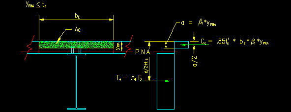
To find the location of the PNA we need to write the axial force equilibrium equation for the ultimate strength condition (i.e., the steel is fully yielded and the maximum concrete strain = -.003). To do so, we need to guess where the PNA will end up. Let's assume, for now, that the PNA is in the slab as shown in Figure 10.8.1.2 below:
SF = 0 = Ts + Cc = AgFy - (0.85f'c)Ac = AgFy - (0.85f'c)(bE b1ypna)
ypna = AgFy / (0.85f'c * bE * b1)
ypna = (7.68 in2)(50 ksi) / [0.85(3.5 ksi)(48 in)(.85)]
ypna = 3.16 in < ts = 4" ... ypna is in the slab... our assumption was good!
Now we can compute Ts and Cc (they will be equal in magnitude if we did the math above correctly).
Ts = (7.68 in2)(50 ksi) = 384 k
Cc = -0.85(3.5 ksi)(48 in)(.85)(3.16 in) = -384 k
Figure 10.8.1.2
Beam Section and Internal Force Diagram

Mn, then, is the magnitude of the couple formed by the two internal forces:
Mn = (Ts or Cc) * (distance between the forces)
Mn = (384 k) * (15.7"/2 + 4" - 0.85*3.16"/2) / (12"/ft) = 336 ft-k
This is the nominal flexural capacity of the member. As a side note, the plastic yielding strength of the section without considering composite action is
Mn = FyZx = (50 ksi)(44.2 in3) / (12"/ft) = 184 ft-k
The consideration of composite action increases the beam flexural capacity by 83%. This is significant.
Now, let's see what the demand is. The controlling distributed load will result from ASD LC-2:
wa = wD + wL = pD*tw + pL*tw = (75 psf)(4 ft) + (50 psf)(4 ft)
wa = 500 plf
The maximum moment for a uniformly loaded, simply supported, single span beam can be computed by:
Ma = wa L2 / 8 = (0.50 klf)(40 ft)2 / 8 = 100 ft-k
Since W is 1.67 for flexure in composite beams (SCM I3.2a), the required nominal capacity is:
Req'd Mn = Ma W = (100 ft-k)(1.67) = 167 ft-k
Finally the ratio Ma/(Mn / W) can be computed:
Ma/(Mn / W) = (167 ft-k) / (336 ft-k) = 0.497
Since the ratio is less than 1.0, the composite beam is adequate for the intended purpose. In fact, only 49.7% of its flexural capacity is being used.
Determine the number and layout of studs required for full composite action
We need to find the number of studs that will transfer the maximum possible horizontal shear force between the beam and slab.
The capacity of a single stud can be computed with SCM equation I8-1. To do this we need the following quantities:
Asa = p * (0.5 in / 2)2 = 0.1964 in2
Ec = (145 pcf)1.5 * sqrt(3.5 ksi) = 3,266 ksi
Now we can compute Qn, the shear capacity of a single stud:
Qn = min[ 0.5(0.1964 in2)*sqrt[(3.5 ksi)(3,266 ksi)], (1)(1)(0.1964 in2)(65 ksi)]
Qn = min[ 10.5 k , 12.8 k] = 10.5 k
The maximum force that can be transferred over the length between the location of zero moment to the location of peak moment is given by:
Max V' = min[0.85f'ctsbE, AgFy] = min[0.85(3.5 ksi)(4 in)(48 in), (7.68 in2)(50 ksi)]
Max V' = min[571 k , 384 k] = 384 k
The required number of studs then is computed by dividing the shear force by the shear capacity of a single stud:
Req'd # = V' / Qn = (384 k) / (10.5 k/stud)
Req'd # = 36.6 studs per half beam
Req'd # = 73.2 studs per beam ----> Use 74 studs!
Note that the distance from the peak moment location to the points of zero moment are the same (half the beam) on each side of the beam FOR THIS CASE! Hence, we can use the same spacing of studs on both sides.
If we start with a stud at each end of the beam the number of spaces required is one less than the number of studs and the spacing of a single line of studs is:
Spacing = (40 ft) / (74 - 1) = .548 ft = 6.58 in O.C.
Per SCM I8.2d, The longitudinal spacing must be greater than, or equal to, six stud diameters (3" in this case). The longitudinal spacing must also be less than, or equal to, min[8ts, 36"], or 32" in this case. Our 6.58" spacing fit this requirement, so:
Recommendation: Use 74 studs, equally spaced along
the span
and centered on the flange.
Determine the Live Load only deflection
To compute the deflection, you will need to compute the transformed moment of inertia, ITR. To do this you will need the modular ration, n:
n = Es / Ec = 29000 ksi / 3266 ksi = 9
Note that modular ratios are normally rounded to the nearest 0.5.
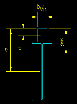
Transforming the concrete into equivalent steel, the width of the concrete block becomes:
b = bE / n = (48 in) / 9 = 5.33 in
Figure 10.8.1.3 shows the general geometry of the section and the reference dimensions. In this case, the dimensions are referenced from the top of the slab. It is acceptable to reference from other locations as long as the reference is stated so that someone reviewing the calculations knows how the calculation was performed.
Figure 10.8.1.3
Transformed Section

Using this width and the geometric properties of the transformed section, we can find the location of the elastic neutral axis so that the transformed moment of inertia can be computed.
| Area | y | y*A | |
| (in2) | (in) | (in3) | |
| Block | 21.33 | 2.00 | 42.67 |
| W16 | 7.68 | 10.85 | 91.01 |
| Total | 29.01 | 133.67 | |
| yena = | 4.61 |
The following calculation computes ITR:
| y relative to: | ||||||
| Area | Io | top of slab | ENA | y2*A | ITR | |
| (in2) | (in4) | (in) | (in) | (in3) | (in4) | |
| Block | 21.33 | 28.44 | 2.00 | -2.61 | 145.03 | 173.47 |
| W16 | 7.68 | 301 | 10.85 | 7.24 | 402.86 | 703.86 |
| Total | ITR = | 877.34 | ||||
With ITR, the deflections of interest can be computed.
The uniform live load for the beam is:
wL = (50 psf)(4 ft) = 200 plf
The mid-span (and maximum) deflection on a simply supported, uniformly loaded beam is computed by
DLL = 5 * (0.20 klf)(40 ft)4(1728 in3/ft3) / [384(29,000 ksi)(877.3 in4)]
DLL = .453 in = L/1060
This is much less than the typical L/360 limit used for live load deflection.
Just for comparison, the deflection without considering composite action would be:
DLL = (.453 in)(877.3 in4) / (301 in4) = 1.32 in = L/364
This deflection would still be acceptable but is pushing the limit. The composite section is much stiffer having a deflection that is almost a third of that of the non-composite section in this case.
Results Summary
The following conclusions concerning the composite floor system can be reached as a result of these computations:
- The floor system has more than adequate to support the moments induced by the floor loads.
- 74 studs are required to develop full composite action.
- The system is very stiff. It deflects much less than required under the influence of transient live loads.
- The system can be modified by either reducing beam size or increasing beam spacing to save on steel.
Additional work that must be done before the design is completely certified as being adequate for this application:
- Check the shear capacity.
- Check to see whether or not shoring is required during construction.
- Check to see if the system is stiff enough to support the total loads that it supports.