|
|
Section 10.6
Deflection Calculations
Last Revised: 05/30/2023
Since deflection is a serviceability, and not a strength, limit state service loads are used to compute the actual deflections. A common mistake made by engineering students using LRFD is to use LRFD factored loads for deflection computations. This is very conservative and not consistent with the theory.
Elastic deflections are inversely proportional to the Moment of Inertia, I, of a flexural member times the material's Modulus of Elasticity, E. In composite members you have two different values for E, thus requiring either a change to the deflection equations or that you "transform" one material into the other. It is typically easier to transform the material than to modify the deflection equations.
The procedure requires that one material is transformed into an "equivalent" area of the other and a transformed moment of inertia, ITR, is computed using the dimensions of the transformed section. Equivalency is based on axial stiffness. The two areas are said to be of equivalent if they have the same axial stiffness, AE. This procedure is presented in most Mechanics of Materials courses that are prerequisite to this text.
You can find more information on transformed sections and the computation of transformed moments of inertia in A Beginner's Guide to Structural Mechanics and Analysis.
In brief review, to transform on material into another, the modular ratio is computed:
n = (E of stiffer material) / (E of the less stiff material)
For composite steel/concrete sections:
n = Es / Ec
Where:
|
Table 10.6.1 |
||||||||||||||||||||||||
|
- Es = 29,000,000 psi
- Ec = wc1.5 33 sqrt(f'c) psi
- wc = unit weight of concrete (pcf). Normal weight concrete is 145 pcf
- f'c is the 28-day compressive strength of a laboratory cured standard cylinder (psi)
Typically, n is rounded to the nearest 0.5 value. Table 10.6.1 lists values for the modular ratio for some common concrete strengths.
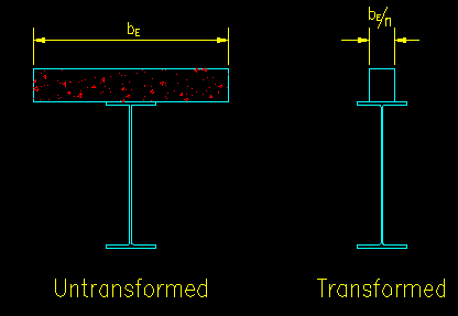
The modular ratio, n, is divided into the "width" dimension (i.e., parallel to the neutral axis) of the concrete section being transformed to find an area of steel that has an equivalent axial stiffness to the concrete. Once this is done, the location of the elastic neutral axis and the transformed moment of inertia, ITR, are computed using principles of statics. Instruction on this can be found in A Beginner's Guide to Structural Mechanics/Analysis.
For example, Figure 10.6.1 shows the untransformed and transformed sections where the concrete has been transformed into an equivalent area of steel.
Figure 10.6.1
Untransformed and Transformed Sections
Click on hotlinks in the image for larger views

Once the transformed moment of inertia, ITR, is computed it can be used in the deflection calculations for the beam as if the beam were all steel.
Note that this transformed moment of inertia is applicable to regions of positive bending. For negative bending regions of the beam, the concrete is ignored (i.e., it is considered to have no tensile strength) and the moment of inertia for the steel beam alone should be used. This can result in segmental integration to determine deflections on continuous beams or other beams with both positive and negative bending regions.