|
|
|
|
|
|
|
|
|
|
|
Section 8.6.4.2
Column Bearing on Concrete
Last Revised: 05/30/2023
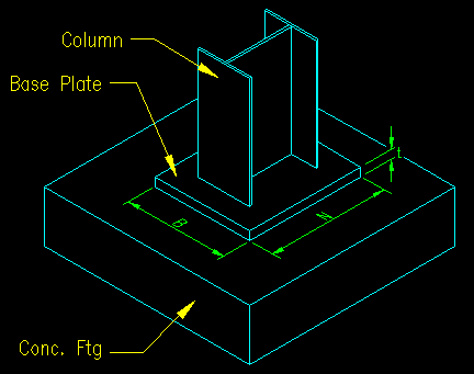
Bearing plates are also frequently used to transfer column forces to concrete footings as shown in Figure 8.6.4.2.1. An excellent discussion on the procedure for designing column base plates can be found starting on SCM page 14-4. SCM Figure 14-3 on SCM page 14-5 shows the critical dimensions.
Figure 8.6.4.2.1
Typical Column Bearing on Concrete Footing.

Note that the base plate is a double cantilever in TWO DIRECTIONS. This means that flexural strength must be checked in both directions when choosing the plate thickness.
Selecting Length, B, and Width, N, of the Plate
As there are two variables (B and N) for the footprint of the contact surface, there are an infinite number of combinations for the values of B and N that will satisfy the strength limit state for bearing on concrete (SCM equations J8-1 and J8-2). Consideration is also given to the size and shape of the column and the location of anchor bolts.
The typical footing is larger than the associated column base plate. The means that A2 is greater than A1 and SCM equation J8-2 applies. The definition and computation of A2 was covered in BGSCM 8.6.4.1. A2 is geometrically similar to and concentric with A1 and fits on the available concrete surface.
Unlike a beam bearing plate where the N dimension is selected based on strength criteria for the supported beam, there is no compelling criteria for choosing either B or N except that it should support the entire column and be sufficiently large to accommodate anchor bolted connections.
Determining the Thickness, t, of the Plate
The last thing to specify is the thickness of the plate. This is done using the equation for thickness developed in BGSCM 8.6.4. Since there are two principle directions, the equation is applied twice, with the larger thickness being the controlling thickness.
To use the equation for computing thickness from BGSCM 8.6.4, we need to map variables as presented on SCM page 14-5. The two principle directions are the cases where B is the span of the beam and again where N is the span of the beam. If we apply these values along with the other factors given on SCM page 14-5, we get an expression for thickness:

If a shape other than an I shape is used, the maximum cantilevered end length (the value in the square bracket in the equation above) will need to be determined and entered into the equation.
Practical Dimensions
The discussion on SCM page 14-6 has some practical suggestions that should be considered when selecting the final dimensions for column base plates. The same criteria can generally be applied to other base plates as well.
<<< Previous Section <<< >>> Next Section >>>