|
References |
|
|
Section 3.6.4
Example Problem 3.5
Last Revised: 04/08/2018
Reference Files:
3.6.5 Example Problem 3.5|
|
|
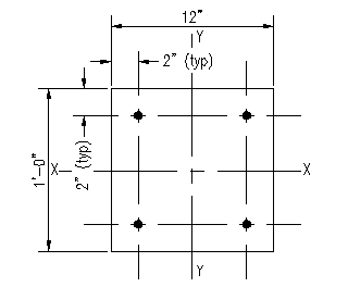
Figure 3.6.5.1 |
 |
|
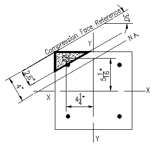
Figure 3.6.5.2 |
|
|
|
Figure 3.6.5.3 |
 |
|
Figure 3.6.5.4 |
|
|
|
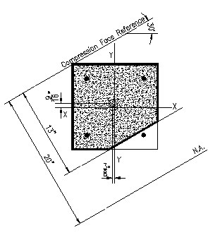
Figure 3.6.5.5 |
|
|
|
Figure 3.6.5.6 |
Given: The column section shown is Figure 3.6.5.1 is made from concrete with f'c = 8,000 psi. The reinforcing steel consists of #5 bars made from ASTM A615 Gr. 60 rebar arranged as shown. The neutral axis is rotated 30 degrees from the principle X-X axis.
Wanted: Compute the nominal strengths associated with an neutral axis located a distance c of
- 4 inches
- 10 inches
- 20 inches
- 100 inches
Solution:
This problem is designed to illustrate computation of the nominal strengths when the axis is not parallel to a principle axis. The geometry gets to be a bit tricky so the computation of areas and distances can be more involved than seen in the prior problems. Otherwise the same basic steps used previously are followed.
Compute b1 for all cases: b1 = 0.65 (See ACI 318-14 22.2.2.4.3)
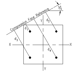
For all the cases, the distance from the compression face to the rebar is the same. Figure 3.6.5.2 shows the distances graphically. The distances, to the nearest 1/16th inch are:
d1 = 2.75"
d2 = 6.625"
d3 = 8.375"
d4 = 13.69"
Case (a)
Refer to Figure 3.6.5.3 for the geometric relationships for this case. Note that graphical means (a CAD program) were used for the geometric computations for this problem.
c = 4"
a = 0.65*(4") = 2.6"
Ac = 7.81 in2
Coordinates of Center of Area relative to principle axes: (-4.25", 5.063")
The solution is easiest done in a tabular form:
| Area | dcf | strain | stress | Force | y arm | Mnx | x arm | Mny | |||
| (in2) | (in) | (ksi) | (k) | (in) | (in-k) | (in) | (in-k) | ||||
| Concrete | 7.81 | -6.8 | -53.11 | 5.06 | 268.86 | -4.25 | -225.71 | ||||
| Bar 1 | 0.31 | 2.75 | -0.00094 | -27.19 | -8.43 | 4 | 33.71 | -4 | -33.71 | ||
| Bar 2 | 0.31 | 6.625 | 0.001969 | 57.09 | 17.70 | 4 | -70.80 | 4 | -70.80 | ||
| Bar 3 | 0.31 | 8.375 | 0.003281 | 60.00 | 18.60 | -4 | 74.40 | -4 | 74.40 | ||
| Bar 4 | 0.31 | 13.69 | 0.007268 | 60.00 | 18.60 | -4 | 74.40 | 4 | -74.40 | ||
| Pn = | -6.64 | kips | 380.58 | -330.22 | |||||||
| Mnx = | 31.71 | ft-k | Mny = | -27.52 | ft-k |
Case (b)
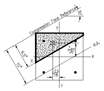
Refer to Figure 3.6.5.4 for the geometric relationships for this case. Note that the graphical means (a CAD program) used for the geometric computations does not account for the holes in concrete compression area. To work around this, we will offset the effect of these holes in the tabular computation. In this case only one bar is located within the Whitney compression block.
c = 10"
a = 0.65*(10") = 6.5"
Ac = 48.52 in2
Coordinates of Center of Area relative to principle axes: (-1.69", 3.56")
| Area | dcf | strain | stress | Force | y arm | Mnx | x arm | Mny | |||
| (in2) | (in) | (ksi) | (k) | (in) | (in-k) | (in) | (in-k) | ||||
| Concrete | 48.52 | -6.8 | -329.94 | 3.56 | 1175.40 | -1.6875 | -556.77 | ||||
| Hole-Bar1 | 0.31 | 2.75 | 6.8 | 2.11 | 4.00 | -8.43 | -4 | 8.43 | |||
| Bar 1 | 0.31 | 2.75 | -0.00218 | -60.00 | -18.60 | 4 | 74.40 | -4 | -74.40 | ||
| Bar 2 | 0.31 | 6.625 | -0.00101 | -29.36 | -9.10 | 4 | 36.41 | 4 | 36.41 | ||
| Bar 3 | 0.31 | 8.375 | -0.00049 | -14.14 | -4.38 | -4 | -17.53 | -4 | -17.53 | ||
| Bar 4 | 0.31 | 13.69 | 0.001107 | 32.10 | 9.95 | -4 | 39.81 | 4 | -39.81 | ||
| Pn = |
-349.96 |
kips | 1300.05 | -643.66 | |||||||
| Mnx = | 108.34 | ft-k | Mny = | -53.64 | ft-k |
Case (c)
Refer to Figure 3.6.5.5 for the geometric relationships for this case. In this case there are three bars located in the compression area.
c = 20"
a = 0.65*(20") = 13"
Ac = 130.71 in2
Coordinates of Center of Area relative to principle axes: (-0.375", 0.563")
| Area | dcf | strain | stress | Force | y arm | Mnx | x arm | Mny | |||
| (in2) | (in) | (ksi) | (k) | (in) | (in-k) | (in) | (in-k) | ||||
| Concrete | 130.71 | 6.8 | 888.83 | 0.00 | 0.00 | 0 | 0.00 | ||||
| Hole-Bar1 | 0.31 | 2.75 | -6.8 | -2.11 | 4 | 8.43 | -4 | -8.43 | |||
| Hole-Bar2 | 0.31 | 6.625 | -6.8 | -2.11 | 4 | 8.43 | 4 | 8.43 | |||
| Hole-Bar3 | 0.31 | 8.375 | -6.8 | -2.11 | -4 | -8.43 | -4 | -8.43 | |||
| Bar 1 | 0.31 | 2.75 | -0.00259 | -60.00 | -18.60 | 4 | 74.40 | -4 | -74.40 | ||
| Bar 2 | 0.31 | 6.625 | -0.00201 | -58.18 | -18.04 | 4 | 72.14 | 4 | 72.14 | ||
| Bar 3 | 0.31 | 8.375 | -0.00174 | -50.57 | -15.68 | -4 | -62.71 | -4 | -62.71 | ||
| Bar 4 | 0.31 | 13.69 | -0.00095 | -27.45 | -8.51 | -4 | -34.04 | 4 | 34.04 | ||
| Pn = |
821.68 |
kips | 58.24 | -39.36 | |||||||
| Mnx = | 4.85 | ft-k | Mny = | -3.28 | ft-k |
Case (d)
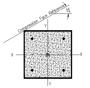
Refer to Figure 3.6.5.5 for the geometric relationships for this case. In this case the entire section is in compression. Since the section is doubly symmetric, the centroid of the concrete compression area coincides with origin of the principle axes.
c = 100"
a = 0.65*(100") = 65"
Ac = 144.0 in2
Coordinates of Center of Area relative to principle axes: (0, 0)
| Area | dcf | strain | stress | Force | y arm | Mnx | x arm | Mny | |||
| (in2) | (in) | (ksi) | (k) | (in) | (in-k) | (in) | (in-k) | ||||
| Concrete | 144 | -6.8 | -979.20 | 0.00 | 0.00 | 0 | 0.00 | ||||
| Hole-Bar1 | 0.31 | 2.75 | 6.8 | 2.11 | 4 | -8.43 | -4 | 8.43 | |||
| Hole-Bar2 | 0.31 | 6.625 | 6.8 | 2.11 | 4 | -8.43 | 4 | -8.43 | |||
| Hole-Bar3 | 0.31 | 8.375 | 6.8 | 2.11 | -4 | 8.43 | -4 | 8.43 | |||
| Hole-Bar4 | 0.31 | 13.69 | 6.8 | 2.11 | -4 | 8.43 | 4 | -8.43 | |||
| Bar 1 | 0.31 | 2.75 | -0.00292 | -60.00 | -18.60 | 4 | 74.40 | -4 | -74.40 | ||
| Bar 2 | 0.31 | 6.625 | -0.0028 | -60.00 | -18.60 | 4 | 74.40 | 4 | 74.40 | ||
| Bar 3 | 0.31 | 8.375 | -0.00275 | -60.00 | -18.60 | -4 | -74.40 | -4 | -74.40 | ||
| Bar 4 | 0.31 | 13.69 | -0.00259 | -60.00 | -18.60 | -4 | -74.40 | 4 | 74.40 | ||
| Pn = |
-1045.17 |
kips | 0.00 | 0.00 | |||||||
| Mnx = | 0.00 | ft-k | Mny = | 0.00 | ft-k |
Solution Summary
| Case | Pn | Mnx | Mny |
| (k) | (ft-k) | (ft-k) | |
| a | -6.64 | 31.71 | -27.52 |
| b | -349.96 | 108.34 | -53.64 |
| c | -943.33 | 3.45 | -1.87 |
| d | -1045.17 | 0.00 | 0.00 |
Discussion
