|
References |
|
|
Section 3.5
Special Cases
Last Revised: 04/08/2018
|
|
|
Figure 3.5.1 |
 |
|
Figure 3.5.2 |
|
|
|
Figure 3.5.3 |
|
|
|
Figure 3.5.4 |
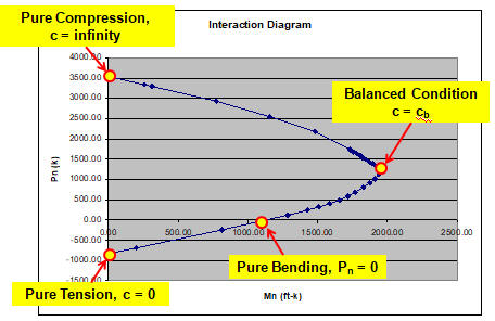
There are four special cases on the interaction diagram which are typically considered. The cases are indicated on the interaction diagram in Figure 3.5.1. They are:
- Concentric Axial Compression,
- The Balanced Condition,
- Pure Bending, and
- Concentric Axial Tension.
All of these cases occur when the neutral axis is at a particular location.
Let's take a look at each of these cases.
Concentric Axial Compression
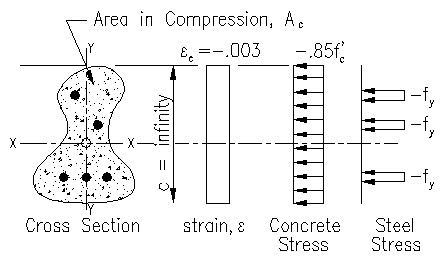
This condition occurs when the neutral axis location approaches infinitely, as shown in Figure 3.5.2.
In this case the entire cross section is within the Whitney stress block and all strain across the entire cross section equals 0.003. A strain of 0.003 exceeds the yield strain of the steel, fy/Es, consequently all the steel in the section has yielded.
Pn = sum(Tsi) + Cc = sum(Asi)fy + 0.85f'c(Ag - sum(Asi))
If the steel is arranged symmetrically about the principle axes, then the compression force is truly concentric and nominal moment capacities, Mnx and Mny, associate with this case are zero. If the steel is not arranged symmetrically, then there will be a moment associated with the maximum axial force.
Mnx = sum(Tsi)(distance from centroidal X axis)
Mny =sum(Tsi)(distance from centroidal Y axis)
Note that either of these moment equations will be zero if there is steel symmetry about the designated principle axis. Most reinforced concrete members design as beams, for example will be symmetrical about one axis while being unsymmetrical about the other.
While the centroid of the concrete area will be slightly non-concentric on the gross cross section if the steel is non-concentric, that term will be very small can be ignored.
The Balanced Condition
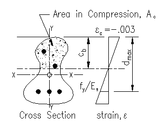
The balanced condition is defined as the condition where the compression face reaches its yield strain, 0.003, a the same time as the furthest piece/group of steel reaches it's yield strain. This condition is illustrated in Figure 3.5.3.
The balanced condition is significant in that it denotes
the neutral axis location
at the transition between brittle and ductile
behavior.
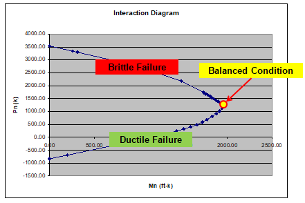
As all points on an interaction diagram denote particular failure conditions, the point associated with the balanced condition is the at the transition from ductile to brittle behavior. The points of brittle and ductile failure modes are indicated on Figure 3.5.4.
Note that, if c is decreased below the balanced c, then the furthest steel is always yielded, denoting a ductile situation. This is very desirable in bending sections. The ductile behavior supplies strength beyond initial cracking and is safer.
If c is increased above the balanced c, then there is no ductile behavior and the member behaves more like a column than a beam. As the brittle behavior acts in a sudden manner with catastrophic consequences, the safety factors associated with the brittle behavior are much more restrictive than for the ductile behavior case.
Later, we will show how the ACI 318 specification applies different safety factors in each region.
The location of the balanced c is straight forward. Using similar triangles:
cb/.003 = dmax/(.003+fy/Es)
cb = .003dmax/(.003+fy/Es) (Equation 3.5.1)
Note that the general shape of the cross section does not enter into the expression. Equation 3.5.1 is shape independent.
The only dependency is that the distances cb and dmax are measured from the compression face and are perpendicular to the neutral axis.
Pure Bending
Pure bending is the case where the sum of the forces on the section equals zero. In other words, where there is no net axial force.
Pn = 0 = sum(TSi) + Cc
Where:
- Tsi is the force in the ith piece of reinforcing steel (positive values are tension)
- Cc is the force in the compression area, bounded by the line at location c, of the concrete.
Each of these terms is a function of the location, c, of the neutral axis. Using the terms present in Section 3.2 this is expressed as:
0 = sum(max[min[fy, Es(c-di)(-0.003/c)], -fy])Asi + .85f'cAc(c)
As seen above, the area of concrete in compression, Ac(c), is a function of c. For complex shapes, this function maybe difficult to write.
When there are bars with different stresses, the terms of this equation multiply. In addition, for each bar set, there are two different assumptions that can be made: the bars yield or they don't yield. In order to solve the equation directly for c, assumptions need to be made (and verified at the end) concerning the yield state of the steel. This makes for many different permutations of the equilibrium equation, each depending on a different set of assumptions concerning the steel's yield state. The result is that it is often difficult to solve this equilibrium equation directly. Trail and error approaches are commonly used, aided by a spreadsheet or other computational program.
Singly Reinforced Rectangular Sections
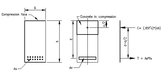
There is one common case where this equation can be easily solved for the location of the neutral axis, c. This common case is for a rectangular singly "under reinforced" section when all the bars yield. Figure 3.5.5 shows the cross section and the resultant internal forces.
 |
|
Figure 3.5.5 |
The under reinforced condition occurs when the location of the neutral axis, c, is less than the location of the balanced neutral axis, cb. Under reinforced means that there steel is limited to ensure that it reaches yield before the concrete reaches the ultimate compressive strain of 0.003. For this case, the equilibrium equation can be written as:
0 = Asfy - 0.85f'cAc = Asfy - 0.85f'c(ba) = Asfy - 0.85f'c(bb1c)
c = Asfy / (.85f'cbb1) (Equation 3.5.2)
The above equation assumes that the tension steel has yielded, so you must verify this assumption by showing that:
c < cb
As most reinforced concrete beams are rectangular and singularly reinforced (or can be approximated as such), once the above condition is verified, the nominal moment capacity, Mn, is computed as couple formed by the opposing internal forces:
Mn = (Ts or Cc)(d - a/2) = Asfy(d - a/2) = .85f'cba(d-a/2)
It is common to use the steel version of the equation:
Mn = Asfy(d - a/2) when c < cb (Equation 3.5.3)
Again... this equation assumes that the steel yields! If this equation is used, you must demonstrate that c < cb.
What happens if c is not less than cb? This is an consider "over reinforced" section. In this case the steel stress fs is less than fy and is a function of the location c. The intital equalibrium equation is written as:
0 = Asfs - 0.85f'cAc = AsEses - 0.85f'c(ba) = AsEs (0.003*d/c - .003) - 0.85f'c(bb1c)
0 = 0.85f'cbb1c2 + 0.003EsAsc - 0.003EsAsd (Equation 3.5.4)
This equation has two roots, one of which will be positive. As above, you must verify your assumption that the steel does not yield, in other words, that c > cb.
The nominal moment capacity, Mn, is again computed as the magnitude of the couple formed by the two internal forces, which in this case is:
Mn = (Ts or Cc)(d - a/2) = AsEs((c-di)(-0.003/c))(d - a/2) = .85f'cba(d-a/2) (Equation 3.5.5)
In summary, the two cases are:
Mn = Asfy(d - a/2) = .85f'cba(d-a/2) when c < cb
Mn = AsEs((c-di)(-0.003/c))(d - a/2) = .85f'cba(d-a/2) when c > cb (Equation 3.5.6)
One way to combine the two equations is:
Mn = min[AsEs((c-di)(-0.003/c)), Asfy] (d - a/2) (Equation 3.5.7)
Example problem 3.6.3 illustrates the application of this section.
Doubly Reinforced Rectangular Sections
Another common beam section is the doubly reinforced rectangular section. There are a variety of good reasons (discussed later) to add steel close to the compression face. As will be demonstrated, increased strength, is not one of those good reasons. While it does tend to add some strength, it is a minor increase for the amount of steel added. The compression zone steel is normally ignored for the more conservative, and simpler, singly reinforced approach.
 |
|
Figure 3.5.6 |
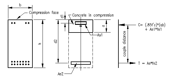
Consider the idealized section in Figure 3.5.6. The section has two bar sets located d1 and d2 from the compression face.
To locate the neutral axis, the equilibrium equation is used.
Pn = 0 =Ts1 + Ts2 + Cc
Pn = 0 = (max[min[fy, Es((c-d1)(-0.003/c))], -fy])As1 + (max[min[fy, Es((c-d2)(-0.003/c))], -fy])As2 + .85f'cAc(c) (Equation 3.5.7)
Note that Ac(c) = ba if As1 is located such that d1 > a. Otherwise Ac(c) = ba-As1.
As written, equation 3.5.7 would be adequate for programming. When programmed, the the value of c is varied until Pn = 0. This form is not suitable for a direct solution for c.
In order for you to solve the equation directly, you would need to make assumptions about the yield state of the steel at each location. This could, theoretically, result in nine different possible equilibrium equations in this case! Some can be discounted outright, but you are still left with the possibility of solving at least four or five quadratic equations then verifying the associated assumptions until you find the one equation which is valid.
Once you have found c, then you can compute the nominal moment capacity, Mn. In this instance, there is no couple to use so moments are taken about the centroidal axis of the member.
Mn = Ts1 (h/2 - d1) + Ts2(h/2 - d2) + Cc(h/2 - a/2)
Mn = (max[min[fy, Es((c-d1)(-0.003/c))], -fy])As1 (h/2 - d1) + (max[min[fy, Es((c-d2)(-0.003/c))], -fy])As2(h/2 - d2) + .85f'cAc(c)(h/2 - b1c/2)
What you will find as you apply this equation is that the moment contribution term for Ts1 is typically small (1%-5% of the total nominal moment capacity, Mn). Adding compression steel simply reduces the concrete stress block without increasing the magnitude of the force in the couple. By reducing the concrete area and the addition of the steel compressive force tends to add a slight increase in distance between the forces of the couple (couple distance in Figure 3.5.6), resulting in a slight increase in nominal moment capacity. Close examination of the equations shows that increase the force of the couple by adding tension steel is much more effective than adding compression steel when trying to increase the nominal strength of a beam. Consequently, the steel associated with Ts1 term can be ignored and the more simplistic approach for a singly reinforced member, ignoring the steel close to the compression face, can be conservatively used.
Concentric Axial Tension
 |
|
Figure 3.4.7 |
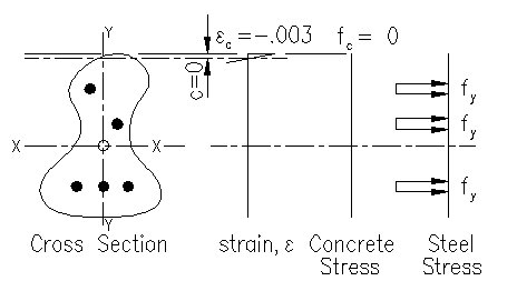
This condition occurs when the neutral axis location approaches zero. In this case, there is no compression area and Ac =0. All the steel has yielded in tension. Figure 3.4.7 illustrates the condition where c approaches zero.
Pn = sum(Tsi) = sum(Asi)fy
If the steel is arranged symmetrically about the principle axes, then the tension force is truly concentric and nominal moment capacity, Mn, associate with this case is zero. If the steel is not arranged symmetrically, then there will be a moment associated with the maximum axial force.
Mnx = sum(Tsi)(distance from centroidal X axis)
Mny =sum(Tsi)(distance from centroidal Y axis)
Note that either of these equations will be zero if there is steel symmetry about the designated principle axis. Most reinforced concrete members designed as beams, for example will be symmetrical about one axis while being unsymmetrical about the other.
