|
References |
|
|
Section 3.6.1
Example Problem 3.2
Last Revised: 04/08/2018
Reference Files:
3.6.2 Example Problem 3.2|
|
|
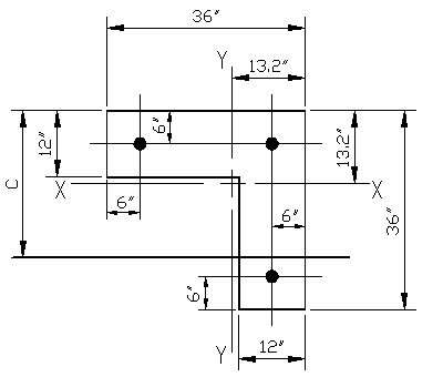
Figure 3.6.2.1 |
Given: The section shown is Figure 3.6.2.1 is made from concrete with f'c = 6,000 psi. The reinforcing steel consists of #10 bars made from ASTM A615 Gr. 60 rebar.
Wanted: For situations where the neutral axis is oriented parallel to the X-X principle axis, determine the nominal strengths (Pn, Mnx, Mny) associated with the following neutral axis locations.
- c= 0"
- c = 10"
- c = 25"
- c = 100"
Solution:
Part (a)
For c=0", the entire section is considered to be in tension with the strain in the steel being beyond the steel strain. None of the concrete contributes to the strength. As all the bars are the same size, the force in each bar is the same:
Ti = (60 ksi) x (1.27 in2) = 67.6 kips/bar
Given that there are three bars:
Pn = 3 x (67.6 kips)
Pn = 202.8 kips
The associated nominal moments can be found by taking moments about each principle axis:
Mnx = (67.6 k)(6" -13.2") + (67.6 k)(6" -13.2") +
(67.6 k)(36" -13.2"-6")
Mnx = -487 in-k - 487 in-k + 1136 in-k = 162 in-k
Mnx = 13.5 ft-k (compression on the "top" face)
Mny = (67.6 k)(36"-13.2"-6") + (67.6 k)(6" -13.2")
+ (67.6 k)(6" -13.2")
Mny = 1136 in-k - 487 in-k - 487 in-k = 162 in-k
Mny = 13.5 ft-k (compression on the "right" face)
Part (b)
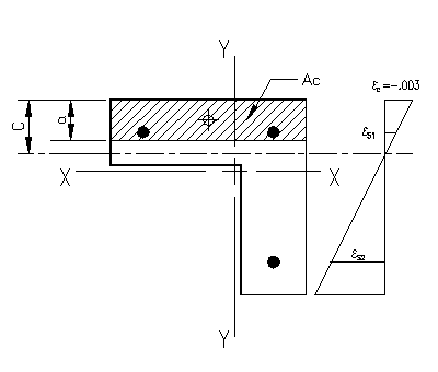
When c=10", there is a concrete compression block. We will start by determining the value of b1 according to ACI 318-14 22.2.2.4.3.
|
|
|
Figure 3.6.2.2 |
b1 = 0.85 - 0.05(6,000-4,000)/1000 = 0.75
Next we compute the value of a according to ACI318-14 equation 22.2.2.4.1:
a = b1c = 0.75(10") = 7.5"
We now know the area bounding the compression area (see Figure 3.6.2.2). We need to compute area and the location of the center of this area.
| Concrete Area and Centroid Computations | |||||||
| Width | Height | Area | Ycf | Ycf*A | XCA | X*A | |
| (in) | (in) | (in2) | (in) | (in3) | (in) | (in3) | |
| A1 | 36 | 7.50 | 270.00 | 3.75 | 1012.50 | -4.8 | -1296 |
| A2 | 12 | 0.00 | 0.00 | 12.00 | 0.00 | 7.2 | 0 |
| AS1 | -1.13 | 6.00 | -6.76 | -16.8 | 18.9336 | ||
| AS2 | -1.13 | 6.00 | -6.76 | 7.2 | -8.1144 | ||
| AS3 | 0.00 | 30.00 | 0.00 | 7.2 | 0 | ||
| 267.75 | 998.98 | -1285.18 | |||||
| Ac = | 267.75 | in^2 | |||||
| Ycf = | 3.73 | in (center of area measured from the compression face) | |||||
| Y = | 9.47 | in (Y location of center of area measured from centroidal X axis) | |||||
| X = | -4.80 | in (X location of center of area measured from centroidal Y axis) | |||||
We can now determine the force in the concrete compression block:
Cc = -.085(6 ksi)(267.75 in2)
Cc = (-5.10 ksi)(267.75 in2)
Cc = -1365.5 k (compression)
From the strain diagram, we can compute the values for the strain in all three reinforcing bars.
eS1 =
-0.003*(10"-6")/10" = -0.0012
eS2 = -0.003*(10"-30")/10" =
0.0060
Next, the stress in the bars can be determined:
fS1 = max[min[-0.0012*(29,000 ksi), fy],-fy]
fS1 = max[min[-34.8 ksi, 60 ksi],-60 ksi] = -34.8.0 ksi
fS2 = max[min[0.0060*(29,000 ksi), fy],-fy]
fS2 = max[min[174 ksi, 60 ksi],-60 ksi] = 60.0 ksi
Finally, we can determine the force in each bar. In the spreadsheet computation, the forces for each of the three bars is computed. However, this can be simplified in this case as there is only bending about the X-X axis and there are two sets of bars, each having the same distance from the neutral axis, strain, and stress within the set.
The area of a #10 bar is 1.27 in2:
TS1 = fS1 * AS1 = (-34.8 ksi)(2
bars)(1.27 in2/bar)
TS1 = (-39.2 kips)(2 bars)
TS1 = -78.4 kips (comp.)
TS2 = fS2 * AS2 = (60 ksi)(1 bar)(1.27
in2/bar)
TS2 = (-67.6 kips)(1 bar)
TS2 = -67.6 kips (tens.)
Note that the the force in each bar is located the bar center.
The stress acting on the concrete compression area is:
fc = -0.85*f'c = -0.85*(5 ksi)
fc = -4.25 ksi
The distribution of this stress, combined with the steel stress, is depicted in Figure 3.6.1.4. Note that the concrete stress is substantially less than the steel stress, however, it is applied over a much larger area.
Now that all the forces and their locations have been determined we can solve the equilibrium equations to determine the nominal strengths associated with the chosen neutral axis location.
Refer to Figure 3.6.2.5 for the forces used to compute Pn and Mnx. Tension positive notation is used with all the vectors being shown in their positive (tensile) direction as acting on the section face.
To find Pn, the nominal axial force located at the section centroid, the sum of forces equilibrium equation is written using tension positive notation as:
0 = -Pn + Cc + TS1 + TS2
Pn = (-1365.5 k) + (-74.4 k) + (+67.6 k)
Pn = -1376 kips (compression)
Next, we determine Mnx, the moment about the "X" axis. This is done by computing moment equilibrium about the "X" axis using right hand rule moment notation.
0 = -Mnx - TS1*(13.2"-6") - TS2*(13.2"-30") - Cc*(13.2"-3.73")
Mnx = -(-74.4 k)*(7.2") - (67.6 k)*(-16.8") - (-1,365.5
k)*(9.47")
Mnx = 565 in-k + 1,136 in-k + 12,930 in-k
Mnx = +14,631 in-k = +1219 ft-k
As there is not symmetry of areas and forces, there will be a moment about the centroidal "Y" axis in this case. We will need to consider the forces in the individual bars, as there are no "bar sets" about for bending about the Y-Y axis. Positive moments will be those which cause compression on the right side of the section, as drawn.
0 = -Mny - (-39.2 kips)*(13.2"-6") - (-39.2
kips)*(13.2"-30") - (67.6 kips)*(13.2"-6") - (-1,365.5 k)*(13.2"-3.73")
Mny = 282 in-k - 659 in-k - 487 in-k + 6,554 in-k
Mny = +5,691 in-k = +474 ft-k
Part (c)
|
|
|
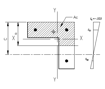
Figure 3.6.2.3 |
 |
|
Figure 3.6.2.3 |
The computations for c=25" are essentially the same as in part (b) of the problem, with the exception that the concrete area is no longer a rectangle. Figure 3.6.2.3 shows the compression area and strain diagram for the problem.
The solution follows the same basic steps:
- Determine the value of a.
- Compute the concrete compression area bounded by the axis at a and the physical limits of the section less the area of any reinforcing bars included in the area.
- Compute the total concrete compressive force and it's location on the section.
- Compute the strains in all the reinforcing bars.
- Compute the stress and force in all the reinforcing bars.
- Determine the value of Pn, the nominal axial strength, using axial force equilibrium.
- Determine the values of Mnx and Mny, the nominal bending strengths, using moment equilibrium about the appropriate axes.
The spreadsheet for this problem has been set up to solve this particular problem, however, it is encouraged that problem be verified by hand calculations until you are comfortable with the process.
In particular, it is easier to find the area of concrete, Ac, by dividing the L-shaped area into two rectangle. Each rectangle can be considered a separate compressive force, or they can be used to compute a total Ac and its centroid. The provided spreadsheet takes the second option, however either approach is valid.
Part (d)
The first thing to notice about the case where both c and a are beyond the physical limits of the section is that Ac then equals the gross area of the section less the area of the reinforcing bars.
For the case of c=100", the computed value of a=75". The section is only 36" deep in the direction measured. The value of a is not used in the area computation at this point because it would give a falsely larger concrete area. Ac can never exceed the gross area of the section. In this case, the center of Ac is at, or very near, to the gross section centroid, depending on the rebar arrangement.
The second thing to notice is that, as c gets large, the strains in all the steel sections will reach a point where they all exceed the yield strain in compression. This means that the stress in the steel will equal -fy.
The solution for this problem follows the same steps as previously mentioned. Hand solutions can be checked against this problem's spreadsheet solution.
Solution Summary
The results for the specified cases are found in Table 3.6.2.1. Note that these are not points for use on 2D interaction curve. They would be best plotted in 3D, if a plot is desired. Without the computation of many more points, for different values of c and orientations of the neutral axis, it is not useful to graph these points. The purpose of this exercise was simply to illustrate the application of the principles of strain compatibility and equilibrium to a problem of general shape.
|
Table 3.6.2.1 Solution Summary |
|||
| c | Pn | Mnx | Mny |
| (in) | (k) | (ft-k) | (ft-k) |
| 0.001 | 202.7 | 13.7 | 13.6 |
| 10.0 | -1376 | 1219 | 474 |
| 25.0 | -2720 | 1349 | 563 |
| 100.0 | -3858 | -12.4 | -14.7 |


