|
References |
|
|
Section 3.6.1
Example Problem 3.1
Last Revised: 04/08/2018
Reference Files:
- 3D AutoCad v7 file for Example 3.1
- AutoCad v7 file for Chapter 3 Example Problems
- Spreadsheet file with Example Problem Solutions
|
|
|
Figure 3.6.1.1 |
 |
|
Figure 3.6.1.2 |
|
|
|
Figure 3.6.1.3 |
|
|
|
Figure 3.6.1.4 |
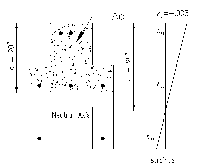
Given: The section shown is Figure 3.6.1.1 is made from concrete with f'c = 5,000 psi. The reinforcing steel consists of #9 bars made from ASTM A615 Gr. 60 rebar. The neutral axis to be oriented parallel to the X-X principle axis.
Wanted:
- For c=25", determine the nominal strengths (Pn, Mnx, and Mny) associated with the given neutral axis location for this section.
- Develop a spreadsheet that will solve the problem for any value of from zero to infinity and plot the 2D interaction curve
Solution:
Part (a)
We will start by drawing the strain diagram in Figure 3.6.1.2. The center of section axis has also been included in this diagram. We will make use of these axes later. Notice that it is coincidence that the middle bar set happens to fall on the section's centroidal axis.
Note that steel located 3" from the compression faces is denoted as S1, steel located 20" from the compression face as S2, and steel located 32" from the compression face as S3. Bars at each of these locations are the same distance from the neutral axis and have the same stress in each bar.
From the strain diagram, we can compute the values for the strain in all eight reinforcing bars.
eS1 =
-0.003*(25"-3")/25" = -0.00264
eS2 = -0.003*(25"-18")/25" = -0.00084
eS3 = -.003*(25-33")/25") = +0.00096
Next, the stress in the bars can be determined:
fS1 = max[min[-0.00264*(29,000 ksi), fy],-fy]
fS1 = max[min[-76.56 ksi, 60 ksi],-60 ksi] = -60.0 ksi
fS2 = max[min[-0.00084*(29,000 ksi), fy],-fy]
fS2 = max[min[-24.36 ksi, 60 ksi],-60 ksi] = -24.4 ksi
fS3 = max[min[+0.00096*(29,000 ksi), fy],-fy]
fS3 = max[min[+27.84 ksi, 60 ksi],-60 ksi] = +27.8 ksi
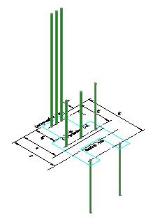
Figure 3.6.1.3 is a 3D depiction of the stress distribution in the bars. Note that the volume (fs*Ab) of 3D stress diagrams equals the force in each bar. Note that upward on the diagram is the compressive, or negative, stress direction.
Finally, we can determine the force in each bar. In the spreadsheet computation, the forces for each of the eight bars is computed. However, this can be simplified in this case as there is only bending about the X-X axis and there are three sets of bars, each having the same distance from the neutral axis, strain, and stress within the set. In this case, each bar in a "bar set" have the same bar area, Ab.
The area of a #9 bar is 1.00 in2, making this computation rather straight forward:
TS1 = fS1 * AS1 = (-60.0 ksi)(3
bars)(1.0 in2/bar)
TS1 = (-60.0 kips)(3 bars)
TS1 = -180.0 kips (comp.)
TS2 = fS2 * AS2 = (-24.4 ksi)(3 bars)(1.0
in2/bar)
TS2 = (-24.4 kips)(3 bars)
TS2 = -73.1 kips (comp.)
TS3 = fS3 * AS3 = (+27.8 ksi)(2 bars)(1.0
in2/bar)
TS3 = (+27.8 kips)(2 bars)
TS3 = +55.7 kips (tens.)
Note that the the force in each bar is located the bar center.
Next we will determine the magnitude and location of the concrete compressive force using the stress block approximation
In this case, we need to compute b1 so that we can compute "a", which bounds the stress block approximation.
b1 = max[0.65, min[0.85,
0.85-(0.05)*(5,000-4,000)/1,000]]
b1 = 0.80
a = b1*c = 0.80 * 25"
a = 20"
The area of concrete in compression (Whitney's Stress Block) is shown as the shaded area in Figure 3.6.1.2.
We can now compute the area of concrete in compression, Ac:
Ac =(8”)(24”)+(12”)(12”) - 6(1.0 in2)
Ac = 330 in2
Note that we deducted the area of the bars included in the compression area so as to obtain only the area of concrete.
Now, the centroid location of Ac must be determined. Using an center of area computation, this distance is determined to be 11.7" from the compression face and centered on the center of area vertical axis. The concrete area and centroid computation was performed as follows:
| Concrete Area and Centroid Computations | ||||||||||
| Width | Height | Area | Ycf | Ycf*A | X | X*A | ||||
| (in) | (in) | (in2) | (in) | (in3) | (in) | (in3) | ||||
| A1 | 12 | 12 | 144 | 6 | 864 | 0 | 0 | Top third of section | ||
| A2 | 24 | 8 | 192 | 16 | 3072 | 0 | 0 | Middle third of section | ||
| A3 | 12 | 0 | 0 | 24 | 0 | 0 | 0 | Bottom third of section | ||
| As1 | -1 | 3 | -3 | -3 | 3 | |||||
| As2 | -1 | 3 | -3 | 0 | 0 | |||||
| As3 | -1 | 3 | -3 | 3 | -3 | |||||
| As4 | -1 | 18 | -18 | -9 | 9 | |||||
| As5 | -1 | 18 | -18 | 0 | 0 | |||||
| As6 | -1 | 18 | -18 | 9 | -9 | |||||
| As7 | 0 | 33 | 0 | -9 | 0 | |||||
| As8 | 0 | 33 | 0 | 9 | 0 | |||||
| Total | 330 | 3873 | 0 | |||||||
| Ac = | 330 | in^2 | ||||||||
| Ycf = | 11.74 | in (center of area measured from the compression face) | ||||||||
| Y = | 6.26 | in (Y location of center of area measured from centroidal X axis) | ||||||||
| X = | 0 | in (X location of center of area measured from centroidal Y axis) | ||||||||
The stress acting on the concrete compression area is:
fc = -0.85*f'c = -0.85*(5 ksi)
fc = -4.25 ksi
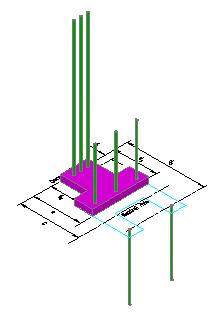
The distribution of this stress, combined with the steel stress, is depicted in Figure 3.6.1.4. Note that the concrete stress is substantially less than the steel stress, however, it is applied over a much larger area.
The resultant concrete force is:
Cc = fc * Ac
Cc = (-4.25 ksi) * (330 in2)
Cc = -1403 kips
Now that all the forces and their locations have been determined we can solve the equilibrium equations to determine the nominal strengths associated with the chosen neutral axis location.
|
|
|
Figure 3.6.1.4 |
Refer to Figure 3.6.1.5 for the forces used to compute Pn and Mnx. Tension positive notation is used with all the vectors being shown in their positive (tensile) direction as acting on the section face.
To find Pn, the nominal axial force located at the section centroid, the sum of forces equilibrium equation is written using tension positive notation as:
0 = -Pn +Cc + TS1 + TS2 + TS3
Pn = (-180 k) + (-73.1 k) + (+55.7 k) + (-1403 k)
Pn = -1600 kips (compression)
Next, we determine Mnx, the moment about the "X" axis. This is done by computing moment equilibrium about the "X" axis using right hand rule moment notation.
0 = -Mnx - TS1*|18"-3"| - TS2*|18"-18"|
+ TS3*|18"-33"| - Cc*|18"-11.7"|
Mnx = -(-108 k)*(15") - (-73.1 k)*(0) + (55.7 k)*(15") - (-1403
k)*(5.3")
Mnx = 2700 in-k + 0.00 in-k + 835 in-k + 8785 in-k
Mnx = +12,320 in-k = +1027 ft-k
Note that, due to symmetry of areas and forces, all the forces computed are centered on the centroidal "Y" axis in this case. This means that none of the forces create moment about the centroidal "Y" axis and hence:
Mny = 0.00 ft-k
Part (a) Result:
Pn = -1600 kips (compression),
Mnx = +1027 ft-k,
Mny = 0.00 ft-k
Part (b)
A general spreadsheet for this problem has been created so that the nominal strengths can be determined for any location of neutral axis.
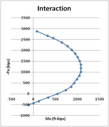
Using the spreadsheet, solutions were found for a sufficient number of cases (i.e. locations of "c") to create an interaction curve for axial force and bending about the "X" axis. Table 3.6.1.1 lists the results and Figure 3.6.1.5 is the graph of the results.
| c | Pn | Mnx | ||
| (in) | (k) | (ft-k) |
|
|
| 0.001 | 480.0 | -74.9 | ||
| 1.8 | 400.6 | 38.3 | ||
| 2.18 | 309.2 | 154.2 | ||
| 3.31 | 140.5 | 368.2 | ||
| 5.06 | 0.0 | 541.7 | ||
| 8.12 | -183.1 | 747.1 | ||
| 11.28 | -352.0 | 876.4 | ||
| 13.64 | -520.3 | 940.8 | ||
| 15.82 | -690.2 | 1002.7 | ||
| 17.53 | -858.7 | 1056.9 | ||
| 19.3 | -1027.7 | 1096.2 | ||
| 20.91 | -1197.2 | 1092.9 | ||
| 22.53 | -1352.6 | 1075.1 | ||
| 24.21 | -1521.8 | 1045.1 | ||
| 25.93 | -1690.8 | 1001.4 | ||
| 27.7 | -1860.9 | 942.1 | ||
| 29.5 | -2030.8 | 866.6 | ||
| 32.4 | -2201.2 | 768.3 | ||
| 35.8 | -2370.5 | 640.0 | ||
| 40 | -2572.5 | 443.0 | ||
| 42.5 | -2681.4 | 315.6 | ||
| 107 | -2894.0 | 69.7 | ||


