| Overview |
| Gravity Loads |
| Lateral Loads |
| Non-Graphical Methods |
|
Powerpoint Illustration (2 MB) |
| Homework Problems |
| Report Errors or Make Suggestions |
Section TA.3
Tributary Areas for Lateral Loads
Last Revised: 11/04/2014
The use of tributary loads is also useful when considering lateral wind and earthquake loadings. The concept is particularly useful for wind loading where the force in the structure generally results from pressure loadings applied to various surfaces.
Consider the rectangular box structure shown in Figure TA.3.1. This structure has horizontal diaphragms at the roof and 2nd floor which provide lateral support of the wall studs which, in turn support the wall sheathing to which a lateral pressure can be applied.
Figure TA.3.1
Example Building Structure
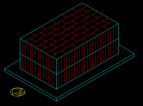
If a uniform pressure is exerted on the walls between any two levels, then the wall studs each support a uniform load and half of their load is transferred to supporting diaphragm at the level above and half to supporting diaphragm at the level below.
For example, Figure TA.3.2 shows pressure P1 applied to the lower level wall and a pressure P2 applied to the upper floor wall. Each wall stud is a simply supported beam (spanning between floors) subjected to a uniform load resulting from the stud tributary area illustrated in Figure TA.3.3.
Figure TA.3.2
Pressures Applied to the South Face
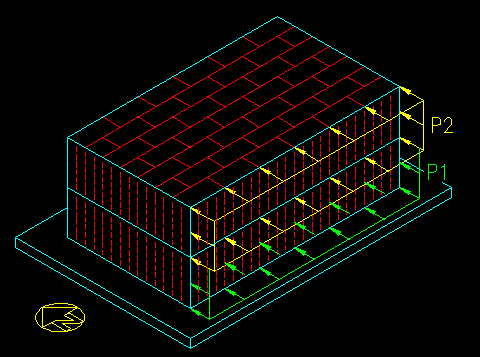
Figure TA.3.3
Area Tributary to a Wall Stud
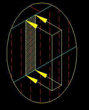
The area tributary to the wall stud equals the sum of half the distance to each adjacent stud (i.e. the tributary width) times the height of the stud. For the beam diagram the distributed load equals the tributary width times the uniform pressure. The load transferred to the support diaphragm equals the stud reaction which equals half the tributary area times the uniform pressure.
In this case, the roof diaphragm (which can be considered to be a beam spanning between the end walls parallel to the direction of the wind force) supports half of the area of the wall below it since it supports have the area of each of the wall studs. Similarly, the second floor diaphragm supports half the area of the upper studs and half the area of the lower studs. Note that the pressures are different on the studs below and above the second floor diaphragm. The area of the lower half of the first floor studs is supported by the foundation. Figure TA.3.4 illustrates the areas tributary to each diaphragm.
Figure TA.3.4
Areas Tributary to the Diaphragms
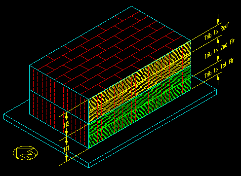
Figure TA.3.5 shows the load diagrams for the two diaphragms. The distributed load on the roof diaphragm, wR, and the second floor diaphragm, w2, equal:
wR = P2 * (Trib Height) = P2 * (H2 /2)
w2 = P2 * (Trib Height) + P1 * (Trib Height) = P2 * (H2 / 2) + P1 * (H1 / 2)
Figure TA.3.5
Diaphragm Load Diagrams
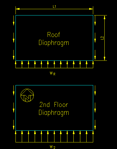
The diaphragms are considered simply supported beams with uniform loads. The diaphragms are supported by the walls at either end of the diaphragm that are parallel to the direction of force. Consequently, the point load applied to each of the supporting walls (known as shear walls) at the diaphragm levels equals half the load supported laterally by the diaphragms. This results in the tributary areas for each wall as shown in Figure TA.3.6.
Figure TA.3.6
Shear Wall Tributary Areas
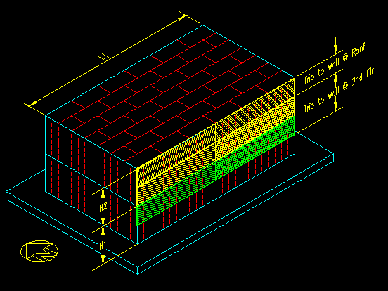
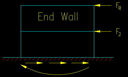
Figure TA.3.7 shows a free body diagram of one of the end end walls with the forces that they receive from the diaphragms. The forces are computed as:
FR = P2 * (H2 / 2) * (L1 / 2)
F2 = [P2 * (H2 / 2) + P1 * (H1 / 2)] * (L1 / 2)
Figure TA.3.7
Shear Wall Free Body Diagram
Using tributary area concepts, any of the forces described above can be computed without necessarily following the whole load path through. All the forces are functions of uniform pressures times areas.
There are other arrangements of structural members that can be devised to resist lateral pressures. The key to getting the right diagrams is to pay attention to the direction of the framing. You can always work your way through the load path, from sheathing to foundation, if there are any questions.