| Overview |
| Development from FBDs |
| Mathematical Derivation |
| Graphical Relatonships |
| Homework Problems |
| Report Errors or Make Suggestions |
Section IFD.1
Overview
Last Revised: 11/04/2014
Internal force diagrams are used extensively in structural engineering. The diagrams help engineers ensure that structural elements of adequate strength are provided to handle the internal force demands shown on them. Unfortunately, this topic seems to be particularly challenging for engineering students.
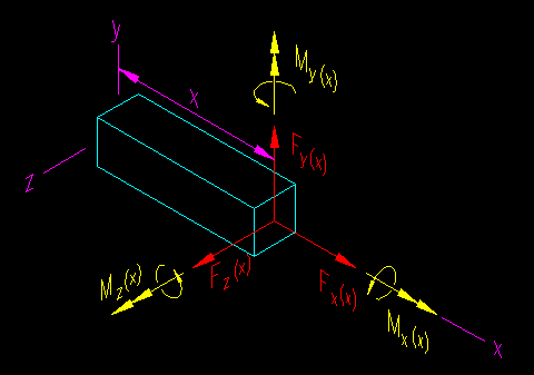
The internal forces of interest in linear structural elements are axial force, shear, torsion, and bending moment. These forces can be found at any point in an element by drawing a free body diagram (FBD) cut at the location where you wish to find the internal force. Figure IFD.1.1 shows the internal forces on the cut end, a location "x" from the origin of coordinates, of general three dimensional a linear member. The internal force diagrams simply graph the values of internal force as they vary along the length of the member.
Figure IFD.1.1
The Six Internal Forces on a 3D Element Section

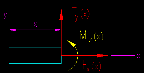
For a system that can reasonably be modeled as a two dimensional system the number of potential internal forces is reduced to three. These are shown in Figure IFD.1.2.
Figure IFD.1.2
The Three Internal Forces on a 2D Element Section

In this chapter several approaches are presented for developing the diagrams. Each method yields the same results and are useful in certain given situations. All the methods start with a loaded structural element for which the reaction forces have already been determined.