|
|
|
Purchase Hard Copy |
Section 4.3
Finding Forces on Bolts
Now that you know HOW a bolt transfers force, let's look at ways in which we can determine the force on a given bolt in a connection. The methods and procedures commonly used for finding forces resulting from applied forces are presented below. Note that these methods and procedures result from principles of structural mechanics and structural analysis and are NOT found in the specification. As far as the specification is concerned, it is the engineer's responsibility to find the forces on individual bolts by any defendable method.
Connections with Concentric Shearing Forces
|
Figure 4.3.1 |
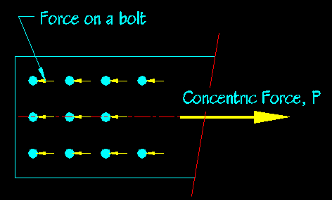 |
Figure 4.3.1 illustrates a connection where the applied force, P, is concentric with the bolt group and the resulting bolt forces are perpendicular to the bolt axis, causing shear in the bolts.
An important assumption when determining the shear in bolts WHERE THE APPLIED CONNECTION FORCE IS CONCENTRIC WITH THE BOLT GROUP is that all shear planes in a connection see the same applied shear STRESS, fv. This is an appropriate assumption because all bolts are constrained by the connected members to deform the same. If they all have the same shear deformations, then they all have the same shear strains and hence they all have the same shear stress. If all the bolts have the same diameter, then all shear planes see the same shear force. This is true for both slip critical and bearing connections.
For a concentrically loaded connection, the shear stress, fv, on the critical shear planes equals the total force being transferred divided by sum of all the shear plane areas:
fv = P / S(Shear Plane Areas)
The SHEAR FORCE on a given SHEAR PLANE = fv Ab
If the bolts all have the same cross-sectional areas, Ab, then the equation becomes:
The SHEAR FORCE on a given SHEAR PLANE = P/(number of shear planes)
The bolt cross-sectional area is critical to the prior calculation. The area of bolt available for use by a shear plane will depend on whether or not the shear plane is in a region of the bolt that is threaded. If the shear plane is in a region that is threaded then there is less area available to resist the applied shear force. The AISC specification requires you to determine whether or not threads are included in the shear plane when computing the capacity of a bearing type connection. This is not an issue in slip critical connections since the force is transferred by friction between the connected members and not by actual shear in the bolt. We will look at this some more when we start computing actual bolt capacities.
Connections with Concentric Tensile Forces
Figure 4.3.2 illustrates a connection where the applied force, P, is concentric with the bolt group and the resulting bolt forces are parallel to the bolt axis, causing tension in the bolts.
Figure 4.3.2
Concentrically Loaded Tensile Connection
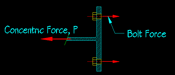
If a connection is concentrically loaded then the tensile stress, ft, in each bolt equals the applied tensile force divided by the sum of the bolt cross-sectional areas.
ft = T / S(Bolt cross-sectional Areas)
TENSILE FORCE on a given BOLT = ft Ab
If all the bolts have the same cross-sectional area, Ab, then the equation becomes
The TENSILE FORCE on a given BOLT = T/(number of bolts)
Combined Concentric Shear and Tension
The interaction of applied shear and tension creates a situation where the principle stress is neither perpendicular nor parallel to the axis of the fastener. Some means has to be used to account for this interaction. Figure 4.3.3 shows a connection where the bolts see both shear and tension. The force on the connection is concentric with the bolt group but has both tensile and shear components.
Figure 4.3.3
Connection with Combined Shear and Tension

For this connection, you will need to break the applied force into its components that are in perpendicular and parallel to the bolt axis. The tensile and shear stress in each bolt will be the same:
fv = Pshear/S(Shear Plane Areas)
ft = Ptension/S(Ab)
To find the applied shear and tensile forces on a particular bolt, simply multiply the stresses by the area of the bolt being considered. If all the bolts have the same cross-sectional area, then the tension force per bolt equals the connection tensile force divided by the number of bolts and the shear force per bolt equals the connection shear force divided by the number of bolts.
In Plane Eccentrically Loaded Connections
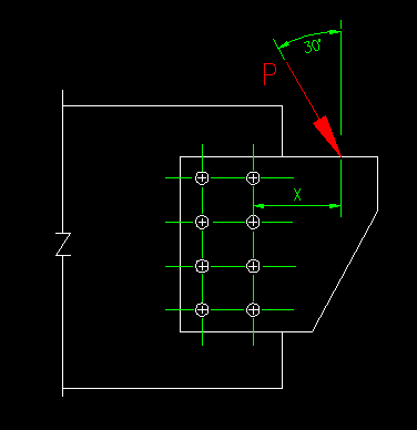
Determining the shear on bolts where the shearing force is in plane with the contact surface but not concentric with bolt group must include the effects of the rotation caused by the eccentricity. Figure 4.3.4 shows one such connection.
Figure 4.3.4
In Plane Eccentrically Loaded Connection
There are two methods that have been developed: The Elastic Method and the Instantaneous Center of Rotation Method. Both methods are covered in the Bolt section of the SCM (starting on SCM pg 7-7).
The Elastic Method uses basic mechanics and superposition to estimate the shear stress in each bolt. The load is moved (by components) to the center of gravity of the bolt group and a moment added to account for the eccentricity. The stresses for each case are then determined and vectorally added together.
Figure 4.3.5
Force Components of the Elastic Method

Figure 4.3.5 shows how the various parts are separated. For each free body the stresses are determined in each fastener.
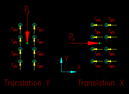
The translational stresses, fvx and fvy, are easily found by dividing the respective applied translational forces by the sum of the bolt cross-sectional areas. The direction component of the stress is parallel to the applied force direction. The shearing force in each fastener equals the stress in the fastener times its cross-sectional area, Ab. Figure 4.3.6 shows the resulting translational bolt reaction forces.
If all the bolts have the same cross-sectional area the forces in the ith bolt due to the load component Px and Py are:
ripy = Py/nb
ripx = Px/nb
Figure 4.3.6
Translational Reaction Forces
The rotational force, M, requires the use of an elastic torsion equation, the assumptions being that
- The stress in each bolt is proportional to its distance from the center of gravity of the bolt group.
- The bolt reaction forces are all perpendicular to their radial line from the center of gravity of the bolt group. The reaction forces should be conveniently broken into their horizontal and vertical components so that they can be vectorally added to the results of the translational computations.
Figure 4.3.7 shows the bolt reactions due to the rotational forces.
Figure 4.3.7
Rotational Reactions
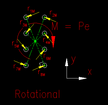
rimx = Ab(Pe)ciy/Ip
rimy = Ab(Pe)cix/Ip
Where:
- cix = the horizontal distance of the ith bolt from the center of gravity
- ciy = the vertical distance of the ith bolt from the center of gravity
- Ip = the polar moment of inertia of the bolt group = Ix + Iy
You will note that the equations listed above are slightly different than found on SCM page 7-9. The equations that they give for the rotational component give the shear STRESS in the bolts. To get the FORCE, you need to multiply the resulting value by the bolt cross-sectional area, Ab.
Make sure that the signs are properly maintained for each of the component forces.
The total force for each bolt is then computed by vectorally adding its components:

Click here to get a powerpoint animation of the Elastic Vector Method concept presented above.
This particular analysis lends itself particularly well to a spreadsheet solution since tables can be developed for the computation of individual bolt forces.
Generally, there will be one or two bolts that has more shear than any of the others. Since you need to show that the applied load is less than the capacity of the bolt and all the bolts have the same capacity, you only need to show that the worst-case bolt has sufficient strength.
When compared with actual test results, the Elastic method is found to be very conservative and to have an inconsistent factor of safety. This is because the use of the principle of superposition assumes that the translational and rotational actions are independent when, in fact, they are not. Hence, the Instantaneous Center of Rotation (IC) method was developed.
The IC Method considers that the translational and rotational events happen simultaneously about an instantaneous center of rotation that is located near a line that is perpendicular to the applied force and passes near the original center of gravity of the bolt group. The method also accounts for "the ductility of the bolt group and the potential for load redistribution" (SCM pg 7-6). The challenge is to find the location of the IC along this line.
For the special cases of an applied load that is vertical or horizontal, the IC lies on the line that is perpendicular to the line of force and passes through the center of gravity of the bolt group. For other loading scenarios the IC lies on the line that is perpendicular to the line of force and passes near the center of gravity of the bolt group. The actual location of the IC is generally found by iterative solution.
Figure 4.3.8 graphically depicts the concepts associated with the two methods.
Figure 4.3.8
Comparison of Methods

Instantaneous Center of Rotation Method
As stated, we know that the IC lies on a line that is perpendicular to the load path and passes near the initial center of gravity of the bolt group. The problem is finding out where the IC lies. This a trial-and-error search problem, which means that it is an excellent candidate to be spreadsheet problem.
Another feature of the IC method is that it computes a relationship between the applied force and the bolt forces instead of the actual bolt forces as was done in the Elastic method. In the IC method we start with bolt force then find the force that would cause that bolt force to occur.
See SCM page 7-7 for a good discussion on this method. As mentioned in the SCM, the method is based on the work of Crawford and Kulak (1968). The figures that are printed on page 7-8 of the SCM will also help you understand the method better.
The basic assumptions of the IC method differ depending on whether a slip critical or bearing connection is being analyzed. The SCM description applies only to bearing connections. Other authors have proposed similar approaches for slip critical connections.
Figure 4.3.9 gives some geometric definitions used in the equations that follow.
Figure 4.3.9
Geometric Definitions
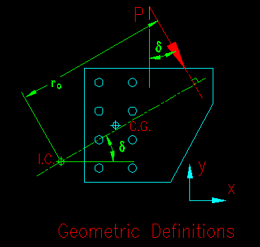
IC method for bearing connections
For a bearing connection the assumptions are:
- The bolt deformations are proportional to their distance from the I.C. leading to the following mathematical relationship:

- The bolt that is located furthest from the I.C. is assumed to have a deformation of 0.34". The deformation in each of the other bolts can be determined by the above equation.
- The bolt force can be determined by a load-deformation relationship that has been experimentally derived from tests on 3/4" dia. A325 bolts in single shear. Note that value of Rult is irrelevant if your end goal is to compute the coefficient 'C' which is the relationship between the maximum bolt force and the applied connection load as both the maximum bolt load and the final computed connection load are linear with respect to Rult and it cancels with computing the ratio coefficient. A true value of Rult is only necessary if trying to determine the load at theoretical failure.

Where Rult = 74 kips for the tested bolts, or
Rult = 0.7(Fu,bolt)AbNs
- The force in any given bolt is perpendicular to a line that passes through the bolt center and the IC.
- Equilibrium is satisfied when the correct IC location is found.

The procedure for applying the IC method is:
- Estimate the location of the IC along the line that is perpendicular to the load path and near the bolt center of gravity.
- Determine the distance and angle from the IC for each bolt
- Set the deformation of the furthest bolt to 0.34"
- Compute the deformation in the other bolts assuming that the deformations are proportional to the distance of the bolt from the IC.
![]()
- Compute the reaction force in each bolt using the load-deformation relationship.
- Compute the horizontal and vertical components of the bolt reaction forces.
- Compute the equilibrium equations, solving for the unknown load P.

- Equilibrium is satisfied if the P computed from each equilibrium equation is essentially the same. If equilibrium is not satisfied then return to step one and try again.
- Once equilibrium is found, compute the coefficient, C, that relates the applied force to the maximum bolt force:

With the coefficient "C" you can find the maximum bolt force for any force "P" or vice versa. We show this is done in Example Problem 4.4.
IC Method for Slip Critical Connections
Since the bolts do not deform in connections designed to not slip (i.e., slip critical connections), the procedure above needs a little change.
When a connection slips, there is slip everywhere except for at the IC. It then follows that at the moment of slip the magnitude of the reaction force associated with each bolt equals it capacity to resist slip. Theoretically, the force that causes slip at a bolt equals the normal force (bolt pretension) times the coefficient of static friction. In the BGSCM 4.7, we will investigate the SCM equations for determining slip capacity.
SCM part 7 does not present methods for determining the forces in bolts for eccentrically loaded slip-critical connections. Reference 5.2 does recommend a modified version of the IC method in which all bolts are assigned the same force and the solution proceeds from there. This essentially eliminates steps 3 and 4 above. Otherwise the procedure is the same.
The problem with this procedure that it often does not converge for loads that are not vertical or horizontal.
A conservative approach to solving eccentrically loaded slip critical problem is to use the coefficient derived from the bearing connection along with slip limit state bolt capacities.
To use the Salmon & Johnson's (ref 5.2) modification of the IC method, use the following procedure:
- Estimate the location of the IC along the line that is perpendicular to the load path and passes through the bolt center of gravity.
- Determine the distance and angle from the IC for each bolt
- Set the magnitude of the reaction force in each bolt equal to rmax (either it's slip resistance capacity or some constant number)
-
Compute the horizontal and vertical components of the bolt reaction forces

- Compute the equilibrium equations, solving for the unknown load P.

- Equilibrium is satisfied if the P computed from each equilibrium equation is essentially the same. If equilibrium is not satisfied then return to step one and try again.
- Compute coefficient that relates the applied force to the maximum bolt
force:

The AISC SCM Coefficient Method
The SCM has computed the coefficient C for a large number of common eccentrically loaded bolt group configurations. These begin on SCM pg 7-31. These extensive tables do not begin to cover all possible cases so there will be times when you need to compute your own coefficients.
Take some time to look at SCM Table 7-6 to see how to determine C for a given situation. You need to know the bolt configuration and its relationship to the load. To use the table, find the bolt group and loading angle you wish to analyze, compute the distance ex (the horizontal distance from the center of the bolt group to the line of action of the force), and determine the number of the bolts in a vertical row. You can then read C from the table (some interpolation may be required). The C value can then be used in the equations at the top of the table. Note, with use of algebra you can reconfigure the equations various ways to either obtain the connection capacity, maximum force in a bolt, or to find a required C when designing the connection.
As we have seen, C relates the force in a bolt to the overall force on the connection. Even without the explanation above, the use of these tables is fairly self explanatory. Spend some time reviewing them.
Another eccentrically loaded condition is when the applied force is out of plane with the faying surface. Figure 4.3.10 shows such a situation.
Figure 4.3.10
Out-of-Plane Eccentricity
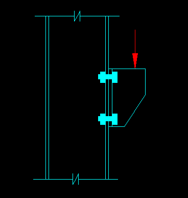
For the bracket shown, the eccentrically applied load that is perpendicular to the bolts, the shear stress is computed by dividing the force by the sum of the bolt areas. The force on a single bolt equals the shear stress time it's cross-sectional area.
The tension results from a bending moment on the face of the connection that is equal to the applied force times the distance the force is from the contact surface of the connection. The SCM provides two methods for analyzing the forces in this problem, starting on SCM pg 7-10.
The Case I method considers the contact compression area between the connected parts. Doing this requires an iterative solution to find the neutral axis so that the moment of inertia of the connection can be found. Once this is accomplished, the tensile stress in each bolt is found using the flexural stress equation, Mc/I. The tensile force in each bolt is found by multiplying the tensile stress by the bolt area.
The Case II method assumes that the neutral axis passes through the center of the bolt group and simplistically assumes that all the bolts above the neutral axis have equal tensile stress and all the bolts below the neutral axis have equal compressive stress. The result is that you can use moment equilibrium to say that the couple created by the bolts equals the moment of the eccentrically applied force. The equilibrium equation is then solved for the bolt forces. This method is more direct and more conservative than the Case I method.
You need to review the SCM sections to apply the methods.