|
|
Section 9.6.2
Example Problem 9.2
The example problem solutions for this chapter are found in the spreadsheet that can be obtained by clicking on the link below.
Download spreadsheet file: BGSCMC09ExProb.xls
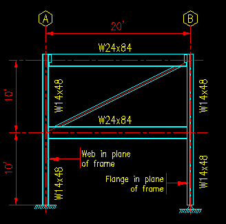
Given: The frame shown in Figure 9.6.2.1. The beams are subjected to a uniform load of 2 k/ft each. Lateral forces of 5k and 10k are applied at grid A at the 2nd floor and roof levels, respectively. The lateral loads are in the direction going from left to right. Out of the plane of the frame, all the columns are pinned at each end and are parts of braced frames. Use ASD.
Figure 9.6.2.1
Example Problem 9.2 Frame
Click on image for larger view
Wanted: Check the capacity of each of the column segments against combined bending and axial force criteria.
Solution: As it is going to be required to compute the forces per column segment, including second order effects, the first step is to perform the two analyses required to use the SCM equations.
Figure 9.6.2.2
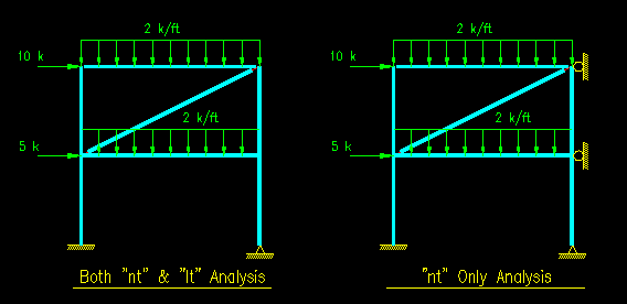
Example 9.2 Analysis Cases
Click on image for larger view
Figure 9.6.2.2 shows the two loading cases considered. Both were input into a commercially available structural analysis program and the results used in the rest of the problem. Note that the top level beam has pinned connections to the columns, as does the brace. The mid level beam has rigid connections to the columns. The column on grid A is bent about its strong axis in the plane of the frame while the column on grid B is bent about its weak axis.
The section properties for the beams and columns are also required. Those properties are listed in the spreadsheet.
The next section in the spreadsheet investigates each of the four column segments. The Mnt, Mlt, Pnt, and Plt were extracted from the two analyses for both ends of each column segment. As there are no transverse loads applied to the column segments between their end connections, the worst case moment and axial force combination will occur at one of the two ends for each segment.
Given that there are fixed connections between the beams and columns, the effective length factors in the plane of the frame are computed using the nomographs given in the SCM commentary (pgs 16.1-241 and 16.1-242). Out of the plane of the frame, the effective length coefficients are all 1.0, by definition given the problem statement.
In the plane of the frame, two different effective length coefficients are computed as required for computing Pe1 and Pe2.
As there is no transverse loading between the segment ends, CM can be taken as less than 1.0. The equation for CM is a function of the end moments. Be careful to make sure that the signs are right!
Eventually, values are obtained for B1 and B2. Note that the computation of B1 is independent of the other columns in the level while B2 is not. B2 is the same for all columns in the level.
Once B1 and B2 have been determined then the values for Pr and Mr can be computed.
Next, we use the information from prior chapters of this text to compute the axial and moment capacities of the members.
Finally, using the values for Pr, Mr, Pc, and Mc, we can choose the appropriate version of SCM Equation H1-1 and compute the value of the combined forces.
In this particular case, all of the column segments appear to be well over designed. If we were in a design mode, new sections would be chosen, the structural analysis repeated with the new sections, the new values of Pr, Mr, Pc, and Mc computed, and the combined force equation re-checked. This cycle would be repeated until the best section is chosen.

