|
|
Section 6.3
Local Buckling
Last Revised: 04/19/2021
|
Figure 6.3.1 |
|
|
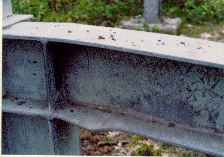
The cross-sections of steel shapes tend to consist of an assembly of thin plates. When the cross-section of a steel shape is subjected to large compressive stresses, the thin plates that make up the cross-section may buckle before the full strength of the member is attained if the thin plates are too slender. When a cross-sectional element fails in buckling, then the member capacity is reached. Consequently, local buckling becomes a limit state for the strength of steel shapes subjected to compressive stress.
Figure 6.3.1 shows an example of flange local buckling. This member failed before the full strength of the member was realized because the slender flange plate buckled first.
In the Euler equation the parameter (L/r) is known as the slenderness of the member. For a plate, the slenderness parameter is a function of the width/thickness (b/t) ratio of a slender plate cross-sectional element. In the SCM member cross-sections are classified, as introduced in the prior section, as being COMPACT, NON-COMPACT, or SLENDER based on the width/thickness ratios of the plate elements that make up their cross-sections and how those elements are connected to the rest of the cross-section. All cross-sections can be classified solely on cross-sectional dimensions and type of steel being used.
|
Figure 6.3.2 |
|
|
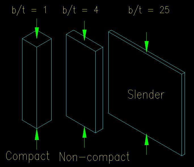
Members with plates having b/t ratios between 0 and lp are said to be "compact" and can be expected to not exhibit any buckling behavior. Their compressive strength is limit by the material compressive strength as seen in Figure 6.1.3.
Members with plates having b/t ratios between lp and lr are said to be "non-compact" and exhibit both plastic and elastic buckling behavior. Their compressive strength is limited by inelastic buckling.
Members with plates having b/t ratios greater than lr are said to be "slender" and exhibit elastic buckling behavior. Their compressive strength is limit by elastic buckling.
Figure 6.3.2 gives a general depiction of the difference between compact, non-compact and slender elements. In the figure, all three plate elements have the same length and the same cross-sectional area, however the width/thickness ratios are different.
Stiffened vs. Unstiffened Elements
The SCM defines two different types of plate elements in a cross-section: Stiffened and Unstiffened. See SCM B4.1a and B4.1b (SCM pages 16.1-16 & 16.1-18) for the definitions. If a plate's edges are restrained against buckling, then the force required to buckle the plate increases. If one edge is restrained (i.e., an "unstiffened" plate element) the force to cause out-of-plane buckling is less than that required to buckle a plate with two edges restrained against out-of-plane buckling. An intersecting plate at a plate edge adds a significant moment of inertia out of plane to the edge which prevents deflection at the attached edge.
Figure 6.3.3 illustrates the modes of buckling for a stiffened and an unstiffened plate element.
Figure 6.3.3
Plate Buckling Modes
Click on image for larger view
Figure 6.3.4 shows a buckled unstiffened element from an experiment. In this experiment, an "L" shaped cross-section was created with thin wood plates. Each of the wood plate elements is "unstiffened" since only one edge is restrained (by the intersecting plate) against out of plane buckling. As a uniform axial compression is added to the member, the initial failure mode is local buckling of the plate elements as shown in the image. As both plates have the same b/t ratio, they both buckled at the same time. Note that the member is not slender (is short with fairly larger "r") so the buckling is not general buckling.
Figure 6.3.4
Buckled Unstiffened Element
Click on image for larger view
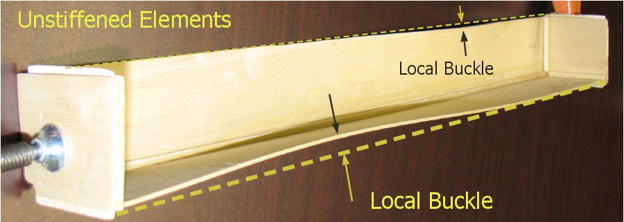
Figure 6.3.5 shows the unstiffened elements on some typical steel sections and the measurement of the element width, b, and thickness, t. Note that a "W" section has four unstiffened elements (i.e., each of the outstanding half flanges, all of equal size), a "WT" has three unstiffened elements, a channel has two unstiffened elements, and an angle has two unstiffened elements. When a section has multiple plate elements, the most slender element will control the definition of the member as being compact, non-compact, or slender.
Figure 6.3.5
Unstiffened Elements
Click on image for larger view
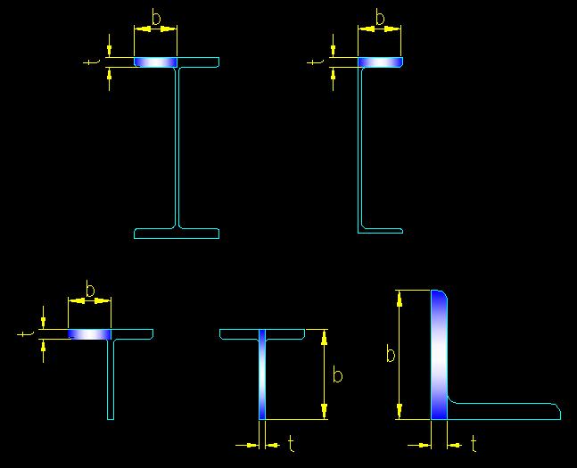
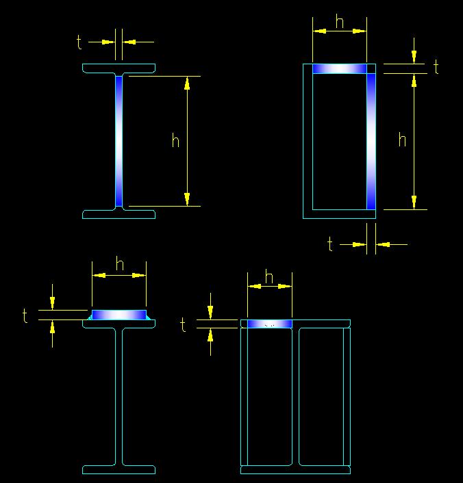
Figure 6.3.6 shows the stiffened elements on some typical steel sections and the measurement of the element width, h, and thickness, t. Note that "W" shapes and channels each have one stiffened plate element in their cross-section. A square or rectangular HSS has four stiffened elements in its cross-section. Normally unstiffened plate elements can be stiffened with the addition of added plate elements as seen in the figure.
Figure 6.3.6
Stiffened Elements
Click on image for larger view
Note that some members have both stiffened and unstiffened elements. The "W" sections and channels are examples of sections with both types of elements in their cross-sections.
Stress Distribution
|
Figure 6.3.7 |
|
|
Another factor effecting buckling is the nature of the compressive stress that the element is subjected to. Euler's equation assumes uniform compression across the section and along the length of the member--all parts of the member are equally stressed. If the compressive stress is not uniform, either on the cross-section or along the length of the member, then the onset of buckling is a bit more complicated and methods for determining buckling must account for the stress distribution. Typically, any non-uniform stress distribution will require greater maximum compressive stress to initiate buckling than that required to initiate buckling under a uniform stress.
As learned in mechanics, normal stress distribution can be characterized as being a function of an applied concentric force and a moment (or moments) about the centroidal axis. Using the basic stress equations for axial force and bending, the force distribution is planar (in 3D) or linear (in 2D). Figure 6.3.7 shows some typical stress distributions on a wide flange section. The top row illustrates combined axial and bending about the strong axis of the member. The lower row illustrates combined axial and bending about the weak axis of the member.
The SCM Section Slenderness Classification
When analyzing a steel section where there is compressive stress on some, or all, of the cross-section, the steel section must be classified as being compact, non-compact, or slender so that the appropriate strength equation can be applied.
SCM B4.1 (SCM page 16.1-16) defines the method used for classifying a section. Where a cross-section consists of multiple plate elements (both stiffened and unstiffened), the most restrictive case (i.e., the most slender definition) defines classification of the section. The actual classification system is tabulated in SCM Tables B4.1a and B4.1b (SCM page 16.1-17). The tables describe the various conditions, how to compute the width/thickness ratio and the limits lp and lr that defined the limits of the slenderness regions. The two tables are used to separate the slenderness classifications for axial compression members from those for flexural members, the difference being that in axial compression members the stress is uniform across the entire section and in flexural members it is not, as shown in the center illustrations of Figure 6.3.7.
The first cases listed in SCM Tables B4.1 refer to unstiffened elements. The remainder refer to stiffened elements. The tables include figures to illustrate the definitions of the various components.
Starting with the 14th edition and continued in the 15th edition, the effects of combined axial and bending forces is not considered.