|
|
Section 5.3
Effective Areas and Size Limitations of Welds
Last Revised: 04/19/2021
This section investigates the mechanics of load transfer between connected members by means of welds. We will look at this problem for each of the basic weld types. The strength of welds is determined by multiplying an effective area by the shear or tensile stress capacity of the weld material.
The effective area is generally determined by multiplying the length of the weld by and EFFECTIVE THROAT, te. The effective throat is a function of the WELD SIZE. The determination of effective throat size is a bit different for each type of weld.
|
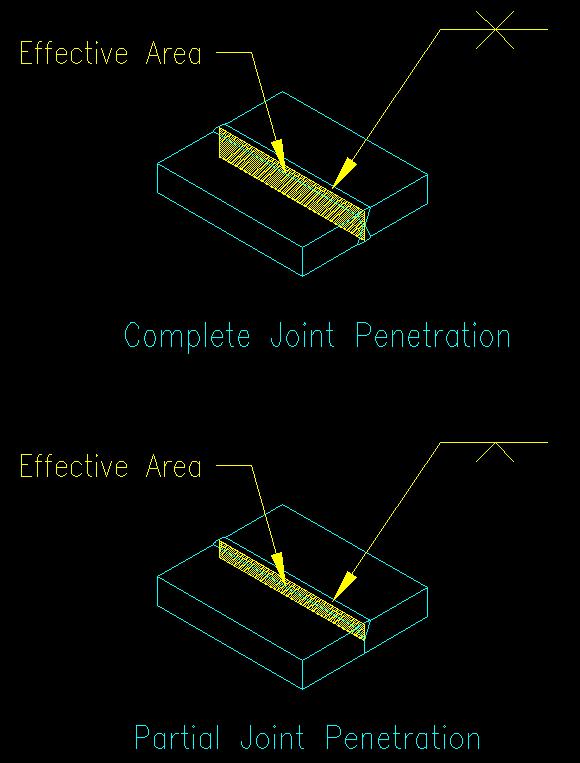
Figure 5.3.1 |
|
|
The goal of the design process is to determine the required length and effective throat thickness for the connection being designed.
The AISC specification requires a minimum effective throat thickness for most types of welds. The intent of the minimum effective throat thickness requirement is to ensure that the weld is of sufficient size to generate enough heat to form a good bond with the base metal. During the welding process, the base metal acts as a heat sink which draws heat away from the connection. If it draws the heat away too quickly, the poor bond is created between the base metal and weld metal.
The effective throat chosen for any weld design will be the LARGER of:
- the minimum requirement for ensuring a good bond with the base metal and
- the minimum required to develop the strength required to transfer the design forces.
Groove Welds
The effective area for the two main types of groove welds is shown in Figure 5.3.1 as specified in SCM J2.1.
For CJP welds, the effective throat equals the thickness of the thinner part joined.
For PJP welds, the effective throat equals the depth of the groove. There is a 1/8" reduction of the depth for the SMAW process if a 45o bevel is used. (See SCM Table J2.1).
SCM Table J2.3 gives minimum required effective throat to ensure a good bond for PJP welds.
Fillet Welds
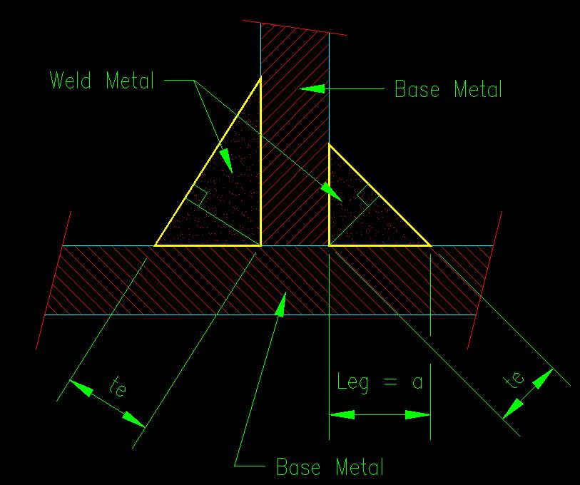
The effective throat, te, for a fillet weld is taken as the least distance from the root of the weld (i.e., where the two connected pieces meet) to the outer surface of the weld as shown in Figure 5.3.2.
Figure 5.3.2
Fillet Weld Sectional Dimensions
Click on image for larger view
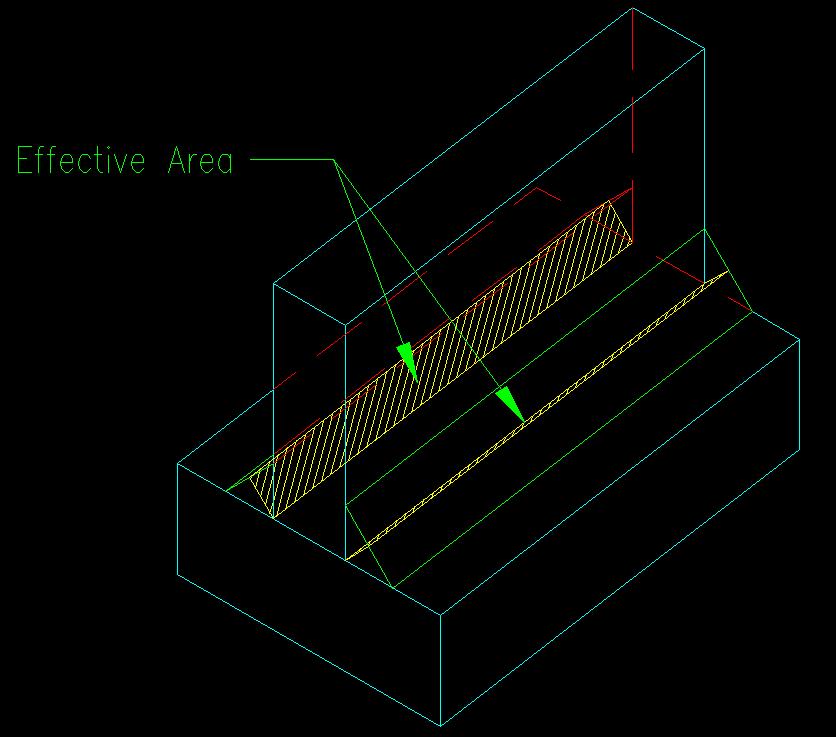
The effective area of your typical fillet weld equals the effective throat times the length of the weld as depicted in Figure 5.3.3. For clarity purposes, the figure shows the effective areas of two fillet welds, one on each side of the vertical piece.
Figure 5.3.3
Effective Area of Fillet Welds
Click on image for larger view
It is important to note that fillet welds are specified by their leg size, a, instead of by the effective throat, te. The vast majority of fillet welds are designed to have equal leg size, which makes te = a*sin(45o) = 0.707a. If the leg sizes are not equal, you will need to determine te using trigonometry.
A change in the 13th edition SCM--and continued in the 15th edition--is the elimination of an explicit allowance for an increase in te when using the SAW process. The prior editions of the specification allowed an increase in te for the SAW process because the process produced welds that had a consistent penetration beyond the root of the weld. The current specification allows for an unspecified increase based on test results that prove this condition. Since the increase is not explicitly stated, we will take the conservative approach of not taking an increase in te for the SAW process.
The specification places a number of limits on the size of fillet welds. These are found in SCM J2.2b.
The MINIMUM ALLOWED SIZE is specified in SCM J2.2b, first paragraph which states that "the minimum size of fillet welds shall not be less than the size required to transmit calculated forces, nor the size shown in Table J2.4" (emphasis added!) The commentary on this section states that the "requirements are not based on strength considerations, but on the quench effect of thick material on small welds." (SCM pg 16.1-422) This means that the weld needs to be big enough to heat the base material sufficient to create a good bond between the base metal and the weld metal. Table J2.4 lists the minimum sized fillet welds. As you look at the table, you see that as the material thickness increases so does the minimum weld size.
A MAXIMUM ALLOWED SIZE is also discussed in the specification. This particular requirement causes some confusion among first time users of the specification. This requirement is based on the AVAILABLE space for the weld. The limit applies only at the EDGES of plates. For example, in Figure 5.3.4(A) the weld is not applied to an edge of either connected plate so the available space for the fillet weld is very large. In other words, tpl is large on both legs of the weld--the end result being that there is not a specified maximum allowed size for the fillet weld in this case. In Figure 5.3.4(B) one of the legs of the weld is along the edge of a plate so the weld size, "a", is limited by the edge thickness tpl as specified.
Figure 5.3.4
Maximum Fillet Weld Size
Click on image for larger view
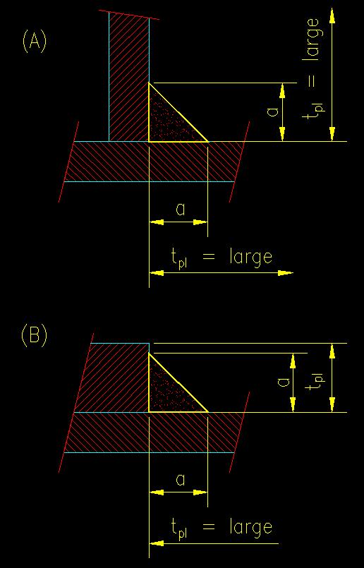
The AISC specification limits the weld size, a, to being equal to tpl if tpl < 1/4" and to tpl-1/16" if tpl > 1/4", where tpl is the minimum of the distances available for the fillet weld leg.
SCM J2.2 has a number of other limitations on fillet welds that you need to be familiar with as well. The rest are fairly self explanatory in the SCM so further coverage will not be made here.
Largest Effective Fillet Weld Size
As will be seen later, the strength of a welded connection is controlled by the weaker of the base metal or the weld (i.e., filler material). The strength of the base metal and the weld are based on their effective areas. Suffice it to say for now that as you increase fillet weld size, the weld strength may, at some point, exceed the strength of the base metal. Increasing the weld size such that the weld strength exceeds the strength of the connected parts will be a waste of resources since it will no longer increase the strength of the connection.
The fillet weld size whose strength equals the base metal strength is called the largest effective fillet weld. It is, in essence, another practical limit on fillet weld size. This is discussed in more detail later.
Plug and Slot Welds
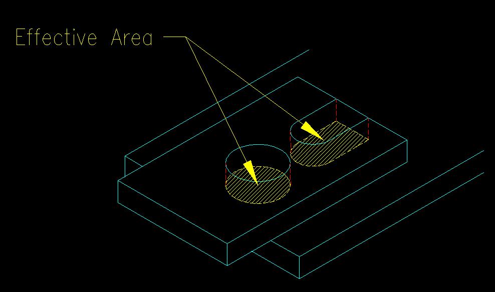
SCM J2.3a specifies the effective area of a plug or slot weld to equal "the nominal cross-sectional area of the hole or slot in the plane of the faying surface." These areas are depicted in Figure 5.3.4.
Figure 5.3.4
Effective Area of Plug and Slot Welds
Click on image for larger view
There are limits on the minimum and maximum sizes of slot welds that can be found in SCM J2.3b.