|
|
Section 9.6.1
Example Problem 9.1
The example problem solutions for this chapter are found in the spreadsheet that can be obtained by clicking on the link below.
Download spreadsheet file: BGSCM14C09ExProb.xls
This problem is a design problem that looks for the lightest weight section that satisfies the SCM criteria for a given loading and geometry. The Effective Length Method is used in this case since it is a single element and first-order analysis is easily accomplished 'by hand.'
Given: An I-shaped section is to be used as a beam-column to support an axial load that consists of 300 kips dead load, 200 kips live load, and 400 kips wind load plus a transverse point load in the strong plane that consists of 150 kips wind load applied at mid span. The beam-column has an overall length 27 ft. The member part of a braced frame and has pinned ends in both principle directions. The weak direction has lateral support at third points. Use LRFD.
Wanted: Find the lightest I-shaped section that can support the given loads with the specified support conditions.
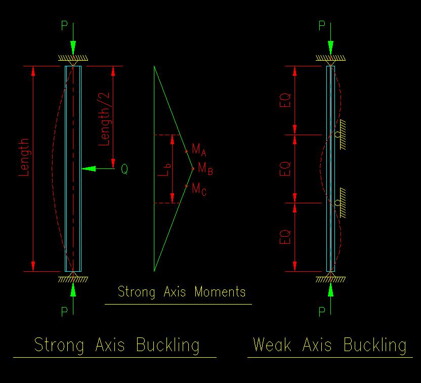
Solution: The first step in the selection process is to set up the analysis spreadsheet for the problem. To better understand the problem so that it can be set up properly, it is useful to sketch the two column buckling diagrams showing the member, its support conditions, and the buckling curve. Figure 9.6.1.1 shows the sketches. As we are going to need to compute moment later, a moment diagram for strong axis bending has also been included. There is not weak axis bending so no moment diagram is needed for that plane.
Figure 9.6.1.1
Example 9.1 Column Diagrams
Click on image for larger view
Computing Demand (i.e. Required Strength)
ASCE 7-05 load combination LRFD LC-4 is the controlling load combination for this member. The magnitudes of the two point loads, without magnification, are computed.
For this case, there are no lateral translational moments since the member is braced in both directions against lateral translation of the joints. This means that all the internal forces are "nt" forces. Consequently, there is no need to compute B2. We do need to actually compute B1, and that only in the strong direction.
The value of CM is taken as 1.0 since the member is subjected to transverse loading between supports in the strong plane.
Pe1 is computed based on an effective length, KL, of 27 ft. The support conditions in the strong directions dictate an effective length coefficient of 1.0. See the buckled shape shown in Figure 9.6.1.1.
With all the requisite parameters in place, we then compute the final design internal forces including the second-order effects.
Member Capacities (i.e. Available Strengths)
The flexural available strength is based on the smaller capacity computed from the Y, LTB, and FLB limit states.
For LTB, the value of Cb is computed using the values for MA, MB, and MC illustrated on the strong axis moment diagram found in Figure 9.6.1.1. Only the center laterally unbraced length was considered because it seems obvious that this will be the controlling segment.
The axial available strength is computed using the requirements of SCM E7. This is done because the spreadsheet must be able to compute the capacity of EVERY I shaped section in the inventory.
Combined Force Computation
Finally, the values from the previous sections are combined together using SCM equation H1-1 and checked to see if the resulting value is less than or equal to 1.0. The spreadsheet can determine which version of the equation to use and provide the correct value.
Finding the Best Section
Once the spreadsheet has been checked for robustness, it can be used to find the best section. There are two approaches that a user can use.
First, the hunt and peck method is one possibility. The user can use the pull down list for the section and select an available section from the list. Note that the list is sorted from lightest to heaviest section. Using this method, the results for any available section can be viewed.
The other approach is a programmed approach. The user need only press the "Find Best Section" button and the program will iteratively change the section, starting with the lightest available section then work up the list of available sections sorted by weight until it finds the first section that satisfies the combined force equation. The macro for performing this search is actually quite simple. The one used in the spreadsheet can be viewed within the Visual Basic editor found in Excel.
Feel free to experiment with the spreadsheet. Try changing any of the values in the grey shaded cells and search for another section.
<<< Previous Section <<< >>> Next Section >>>