|
|
Section 5.8
Example Problem 5.2
Last Revised: 11/04/2014
The example problems presented in this section have a spreadsheet solution. You will need this file to follow along with the presented solutions. You can click on the following link to get the file:
Chapter 5: Excel Spreadsheet Solutions
In addition to the spreadsheet solution this problem also has a downloadable hand solution: Example5_2.pdf
Example Problem 5.2: This example illustrates two ways to "balance" a fillet weld design on a connection that consists of a single angle and gusset plate.
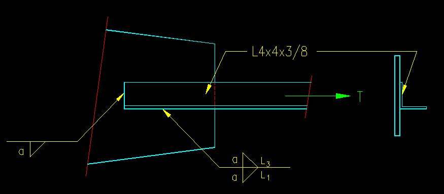
Given: The single angle connection shown in Figure 5.8.2.1. A992 steel and E70 electrodes are used. The gusset plate is 3/8 inch thick. The Tension load is 25 k Dead Load and 40 k Wind Load. Use LRFD.
Figure 5.8.2.1
Angle/Gusset Plate Connection
Click on image for larger view
Wanted: Determine the size and required lengths of the welds so as to minimize the lap of the connection.
a) All fillet welds are the same size
b) Fillet welds may be different sizes
Solution:
For this problem we need to:
- Determine the maximum weld size for each of the three welds.
- Determine the total length of weld required to transfer the load
- Determine the length of each of the three welds so that the connection is balanced
- Draw a detail of the finished designs.
For the end and "top" welds (welds 2 & 3 in the hand calculation), the maximum size weld will be dictated by thickness of the angle leg. The weld cannot be any larger than the thickness of the angle leg less 1/16th of an inch. A minimum weld size is required based on the thickness of the thicker part joined.
For the "bottom" weld (weld 1) there is no geometric limitation on the maximum weld size. The largest effective weld will be the largest practical weld size for this location. It will be used in part (b) of the problem.
For part (a) the all the welds are the same size. The strength of the weld is less than that of the adjacent base metals. The total length of weld is determined by dividing the demand by the weld capacity per unit length.
For both problems, weld 2 is 4" long as the given weld symbol indicates that it runs the full length. The remaining weld is proportioned so that the weld reaction force centriod coincides with the center of area of the angle (which is where the center of force is). A basic centroid computation is used to determine the lengths of welds 1 and 3 in both cases.
The difference between the two cases is that weld 1 is, in part (a), the same size as the other welds. In part (b) this weld is larger than the other two and can be made shorter.