|
|
Section 5.8
Example Problem 5.1
Last Revised: 11/04/2014
The example problems presented in this section have a spreadsheet solution. You will need this file to follow along with the presented solutions. You can click on the following link to get the file:
Chapter 5: Excel Spreadsheet Solutions
In addition to the spreadsheet solution this problem also has a downloadable hand solution: Example5_1.pdf
Example Problem 5.1: This problem looks at a typical lap splice involving an HSS section and a gusset plate. This problem is a little more complex than lapped flat plates, in some ways, but is good for illustrating the computation of maximum effective fillet weld size.
Given: The connection shown in Figure 5.8.1.1 has a gusset plate fitted into a slot in an HSS section. The gusset plate is A992 steel. The HSS is A500 Gr B steel. The electrode is F7. The axial tension force consists of 50 k Dead load and 150 k Seismic Load. Use ASD.
Figure 5.8.1.1
HSS/Gusset Plate Connection
Click on image for larger view
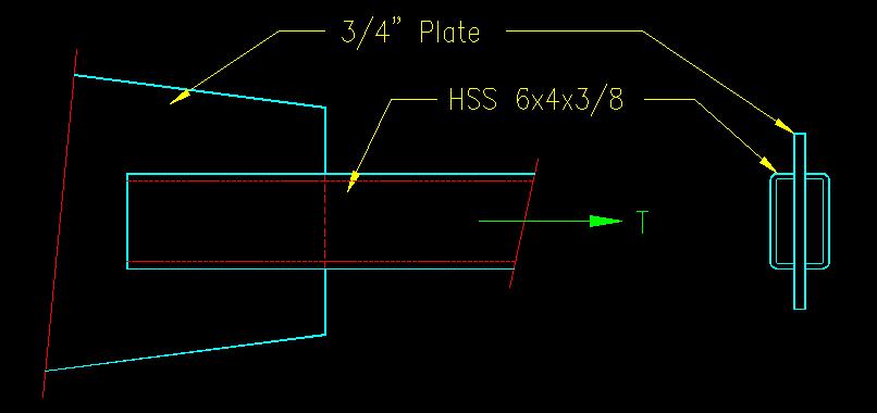
Wanted: Determine the size and required lengths of the fillet welds so as to minimize the lap of the connection. Draw the appropriate fillet weld on your summary detail drawing.
Solution:
For this problem, the following tasks must be completed:
- Determine the design load.
- Determine the capacity of the base metal and the associated lap length
- Determine the size of a weld that is at least as strong as the base metal
By now, the ability to compute design loads should be almost second nature, so we will skip that. You can see what was done in the solution.
In order to make the lap as short as possible, we want to make sure that the weld is designed to be slightly stronger than the base metal since the base metal strength is fixed.
Because of the nature of spreadsheets and hand calculations, the approach taken in each is slightly different, but the results are the same.
In this case there are two base metals to consider: The HSS and the gusset plate, each that see the whole load. Note that each is made of a different steel so that the values of Fy and Fu will vary depending on what strength we are computing.
The HSS has four failure locations, one adjacent to each of the four welds. The wall thickness of the HSS is 3/8". The result is that ABM for the HSS equals (4)(3/8") per 1" of lap.
The gusset plate has two failure locations, each with a weld on each side of the failure surface. The resulting ABM for the gusset plate equals (2)(3/4") per 1" of lap.
The computed capacity per inch of lap shows that the HSS is weaker than the gusset plate and will control the design of the connection. At this point the length of the connection lap can be computed (required capacity / capacity per unit length of base metal).
At this point we want to design a weld that is at least as strong as the HSS base metal. This can be done by setting the equation for weld strength equal to the capacity of the controlling base metal then solving for weld leg size, a.
The only remaining thing to do is to draw the detail for the welded connection. That is shown in the hand calculation with the appropriate weld symbol.