|
|
Section 3.4
Tensile Rupture of a Member
Last Revised: 11/04/2014
Tensile rupture is a strength based limit state similar to the tensile yielding limit state that we just considered. When the cross section is reduced by holes or if not all the cross sectional elements of a particular section (such as the flanges on a W section) are transferring force to a connection, then less of the section is effective in supporting the applied forces. Stress concentrations will also cause localized yielding. Local yielding to relieve stress concentrations is not a major problem for ductile materials so the yielding limit state is not considered where the connections are made. The concern at these locations is actual rupture so the applied forces are compared against the rupture strength in the region of reduced effective section. Figure 3.4.1 illustrations where the concern is for sample flat bar member with bolted end connections.
Figure 3.4.1
Tensile Rupture Regions
The Limit State:
The basic limit state follows the standard form. The statement of the limit states and the associated reduction factor and factor of safety are given here:
| LRFD | ASD |
| Pu < ftPn | Pa < Pn/Wt |
| Req'd Pn = Pu/ft < Pn | Req'd Pn = Pa Wt < Pn |
| Pu / (ftPn) < 1.00 | Pa / (Pn/Wt) < 1.00 |
| ft = 0.75 | Wt = 2.00 |
The values of Pu and Pa are the LRFD and ASD factored loads, respectively, applied to the member. In this case Pn is the nominal tensile rupture strength of the member. Note that the values for ft and Wt are different than previously used. Their more restrictive values indicate that the test results for this mode of failure are more highly variable than those tensile yielding.
Nominal Tensile Rupture Strength, Pn:
The nominal tensile rupture strength, Pn, is computed using AISC specification equation D2-2 and is in force units. In this case, we multiply the effective net cross sectional area, Ae, by the tensile stress, Fu to determine the force that would cause the member to rupture in tension near the connections.
Note that the AISC specification generally uses Fu for the stress level whenever rupture or significant deformation is fundamental to the limit state being considered. This is because the failure mode being considered is rupture (failure, or fracture) of the member is the issue. Moderate local yielding to redistribute forces is tolerated.
Having just introducing Ae, we need to take a detailed diversion into section D3 of the specification.
Area Determination, Section D3
AISC Specification section D3 covers the computation of three different areas: gross area Ag, net area An, and effective net area Ae. We will now look particularly at An and Ae since we've already discussed Ag.
At this point you need to read AISC specification D3.2 on net area. The commentary on this section found on SCM page 16.1-250 is also necessary reading.
The net area computation requires computation of a reduced section due to holes made in the member as well a failure path for the rupture surface.
|
Figure 3.4.2 |
 |
 |
One way to define the net area is it is the gross cross sectional area less the cross sectional area of any holes (effective hole diameter x plate thickness) plus an increase for any diagonal lines in the failure path. Effective hole diameter and failure paths are two new concepts to be considered.
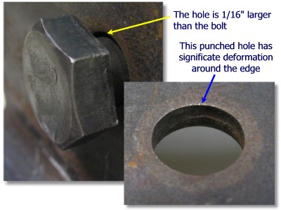
First, let's consider the effective hole diameter. Section D3.2 says that "the width of a bolt hole shall be taken as 1/16 in. larger than the nominal dimension of the hole." (emphasis added). A standard hole is 1/16 inches larger than the bolt it is to accommodate. This means that the effective hole diameter, for An calculations, is to be taken as 1/8" larger than the bolt (i.e. 1/8" = 1/16" for the actual hole diameter plus an additional 1/16" for damage related to punching or drilling.) So, if you specify 3/4" bolts in standard holes, the effective width of the holes is 7/8" (i.e. 3/4" for the bolt diameter + 1/16" for the hole diameter +1/16" damage allowance.)
Figure 3.4.2 shows a typical standard hole and the dimensions that are related to it.
The next concept that needs discussing is the concept of failure paths. Failure paths are the approximate locations where a fracture may occur.
When considering failure paths, you will always start from the side of the member and cut perpendicular to the axis of the member to the center of a hole. The path will then extend from center of hole to center of hole until you take a path to the opposite side which is perpendicular to the axis of the member. The failure path will be located so that it sees the maximum force in the member, in other words all the bolts are on the side of the rupture line that is also connected to another member. Any path that leaves bolts on both sides of the rupture is not feasible unless the member you attach to fails simultaneously along the same path... something that cannot happen for a number of reasons.
Another way to look at this problem is that the failure separates the main member from the connection. All the bolts stay with the connection.
The example problems provided with this chapter show some examples of valid failure paths. Figures 3.10.1.4, 3.10.2.2, and 3.10.3.1 show the various failure paths used.
If there are no bolts in some or all the holes to take force out of the member, then any path through the unfilled holes that leave all bolts on one side of the failure path and the main part of the member on the other side is valid.
Figure 3.4.3 shows a failure path that has a component that is not perpendicular to the line of action for the force. The example problems also have paths that are not straight. The path is said to have a stagger in it if it is not straight. The stagger is characterized by a "pitch" of s and a "gage" of g as shown.
Figure 3.4.3
Failure Path with Staggered Bolts
In this case, we should account for the extra area of steel resisting the applied force. According to AISC specification D3.2, we can add an extra WIDTH term to the net area calculation for this condition. The extra width applied is s2/4g for each gage space that has a diagonal. See D3.2 for a definition of "s" and "g". To convert this width to an area, you multiply it by the thickness of the material over the gage length.
Two basic approaches to computing An are to:
- Multiply the critical path length by the member thickness. This works well for members with constant thickness along the path.
- Add and subtract hole and stagger areas to/from the member's gross cross sectional area. A hole area equals the effective hole width times the plate thickness at the hole. The additional stagger area is the path increment (s2/4g) times the member thickness at the stagger.
Click here to go to a self paced tutorial that will help you to solidify your ability to identify valid failure paths and compute the associated net areas.
In cases where SOME BUT NOT ALL of the cross sectional elements are used to transfer force to/from the member at the connection, then not all the net area is really effective for tensile rupture. This is the result of a phenomena called shear lag. At this point, you should read the SCM commentary on D3.2 found on SCM page 16.1-250.
If you look at the illustrations in SCM figure C-D3.2 you can see what we are talking about when we say SOME BUT NOT ALL of the cross sectional elements are effective in transferring the force.
For example Fig C-D3.2(a) shows a W section bolted (connected) only on the flanges. Hence only two of the three cross sectional elements (i.e. the two flanges and not the web) are transferring the force to the connectors. When this section is used as a tension member, away from the connection, the full cross section is evenly stressed. This means that there is force in the web that must make its way to the flanges so that it can be transferred to the bolts. This happens over the length of the bolted connection via shear lag.
SCM Figure C-D3.2(c) shows a similar member with just one of three cross sectional elements transferring force to the bolts.
SCM Figure C-D3.2(b) shows a situation similar to SCM C-D3.2(b), but for a channel.
Shear lag is a function of both the length of the connection over which it occurs (L) and the eccentricity (x) of the force with relation to connection in section view. SCM Figure C-D3.2 illustrates how x is to be determined for some common cases. The length, l, is computed as the distance from center of first bolt to center of last bolt for bolted connections and as the length of weld for welded connections. The factor "U" is used to reduce An to account for the shear lag effect.
SCM Table D3.1 (SCM page 16.1-29) tabulates how to compute U for different conditions. Study this table carefully. It lists all the various cases where shear lag may be an issue.
Sample Spreadsheet Pn Calculation
There are probably many ways to arrange this computation, but here is one. The shown spreadsheet both computes the "capacity" of the member (in terms of Ps,eq) and checks the capacity against the demand (Pu or Pa). Generally you will do either one or the other, not both. The values in the shaded cells are either entered manually or computed elsewhere and linked to these locations. Note that this spreadsheet only ANALYZES a given member. For design problems where the member size is unknown, you will need to use a little algebra to solve the limit state equation for the required Ag then make decisions from there. In the end, however, you need to show that your final selection satisfies the limit state using some calculation similar to the one shown here.
| Tensile Rupture (Sections D2 & J4.1b) | Pn = AeFu = AnUFu | ||||||||
 |
|||||||||
| Fu = | 58 | ksi | |||||||
| Ag = | 4.5 | in2 | |||||||
| tpl = | 0.5 | in | |||||||
| # members | 1 | ||||||||
| db = | 0.75 | in | |||||||
| Connecting Element? | N | (Y or N) | |||||||
| Net Area Determination | |||||||||
| failure path #1 | |||||||||
| s | g | s2/4g | Total width | tpl | Area | ||||
| (in) | (in) | (in) | (in) | (in2) | |||||
| width segment 1 | 0.000 | 1.500 | 0.000 | 1.500 | 0.500 | 0.750 | |||
| width segment 2 | 0.000 | 3.000 | 0.000 | 3.000 | 0.500 | 1.500 | |||
| width segment 3 | 0.000 | 3.000 | 0.000 | 3.000 | 0.500 | 1.500 | |||
| width segment 4 | 0.000 | 1.500 | 0.000 | 1.500 | 0.500 | 0.750 | |||
| hole 1 | -0.875 | 0.500 | -0.438 | ||||||
| hole 2 | -0.875 | 0.500 | -0.438 | ||||||
| hole 3 | 0.000 | 0.500 | 0.000 | ||||||
| Net Area | 3.625 | ||||||||
| failure path #2 | |||||||||
| s | g | s2/4g | Total width | tpl | Area | ||||
| (in) | (in) | (in) | (in) | (in2) | |||||
| width segment 1 | 0.000 | 1.500 | 0.000 | 1.500 | 0.500 | 0.750 | |||
| width segment 2 | 3.000 | 3.000 | 0.750 | 3.750 | 0.500 | 1.875 | |||
| width segment 3 | 3.000 | 3.000 | 0.750 | 3.750 | 0.500 | 1.875 | |||
| width segment 4 | 0.000 | 1.500 | 0.000 | 1.500 | 0.500 | 0.750 | |||
| hole 1 | -0.875 | 0.500 | -0.438 | ||||||
| hole 2 | -0.875 | 0.500 | -0.438 | ||||||
| hole 3 | -0.875 | 0.500 | -0.438 | ||||||
| Net Area | 3.938 | ||||||||
| 0.85Ag = | 3.825 | in2 | |||||||
| Controlling An = | 3.625 | in2 | |||||||
| U = | 1.000 | ||||||||
| Ae = | 3.625 | in2 | |||||||
| Pn = | 210.3 | kips | |||||||
| Determine Capacity | |||||||||
| LRFD | ASD | ||||||||
| ft = | 0.75 | Wt = | 2 | ||||||
| ft Pn = | 158 | kips | Pn / Wt = | 105 | kips | ||||
| CLF | 1.40 | CLF | 0.90 | ||||||
| Ps,eq = | 112.6 | kips | Ps,eq = | 116.8 | kips | ||||
| Check Capacity | |||||||||
| LRFD | ASD | ||||||||
| ft = | 0.75 | Wt = | 2 | ||||||
| ft Pn = | 158 | kips | Pn / Wt = | 105 | kips | ||||
| Pu | 50.00 | kips | Pa | 35.00 | kips | ||||
| Pu/ftPn = | 31.7% | kips | Pa / (Pn / Wt ) = | 33.3% | kips | ||||
| Okay | Okay | ||||||||