Example #1
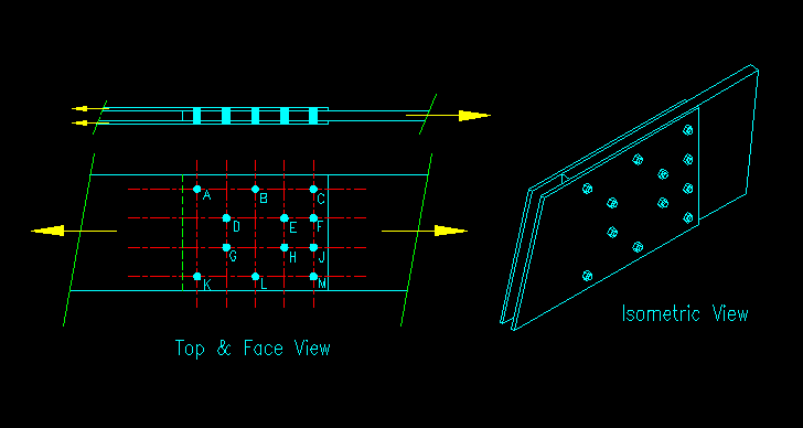
We will start with a simple three member lap connection as shown in Figure FP-1a. The plates are all 12" wide. The side plates are each 3/8" thick and the main plate is 1" thick.

Figure FP-1a
A three member lap splice
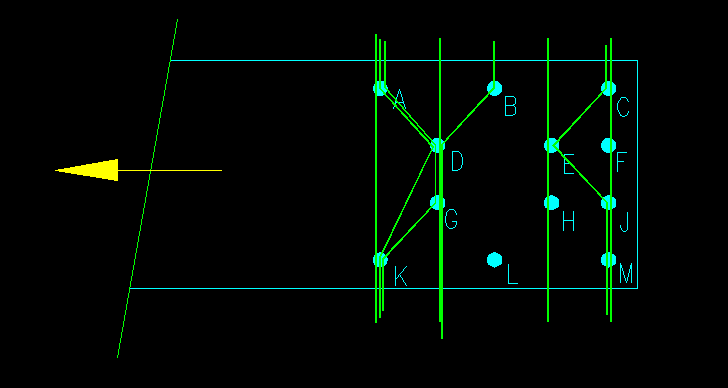
Recalling that the failure path is "MEMBER" dependent, let's look at the two side plates first. The free body of the member end is shown in Figure FP-1b. Possible failure paths are shown with the green lines. Note that they all start and end perpendicular to the direction of force.

Figure FP-1b
FBD of a side plate
Shown are eight possible failure paths. You should be able to come up with a few more. So the question is, which or the indicated paths are valid?
Click the link for each path to see if it is valid or not. Try to figure out which is valid before checking! For the valid paths, you will be asked to compute the failure path length and the associated net area of the plate.
Let's now look at the main plate.
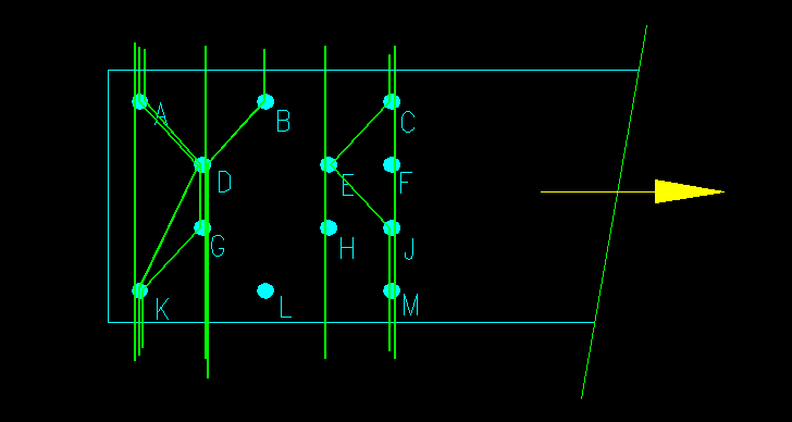
Figure FP-1c show an FBD of the end of the main plate with the same failure paths considered for the side plate. Again there are more potential failure paths than shown, but the given set includes the valid failure path(s).

Figure FP-1c
FBD of the main plate
Click the link for each path to see if it is valid or not. Try to figure out which is valid before checking! For the valid paths, you will be asked to compute the failure path length and the associated net area of the plate.