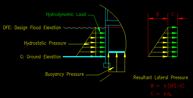
BGASCE7-10 Section 6.4
Hydrodynamic Loads
Last Revised: 11/04/2014
Hydrodynamic loads are those load that result from water flowing against and around a rigid structural element or system. The hydrodynamic loads considered in this section do include the effects of broken and non-breaking waves striking structures, but does not include the effects of breaking waves. Breaking waves are considered separately. ASCE 7-10 Section 5.4.3 simply states that you are to use "a detailed analysis utilizing basic concepts of fluid mechanics" when determining hydrodynamic loads.
There are experimental and analytical means for determining pressures induced by flowing fluids. The pressures are functions of velocity, direction of flow relative to the object, object geometry, and object surface roughness characteristics. Your analysis should use these concepts. Consequently, a study of fluid mechanics will yield the values that you need. This may require the services of specialist who can decide the most appropriate analysis method.
One key variable associated with flood loading is the average velocity of the water. The ASCE 7-10 commentary references two equations that give the lower and upper bounds of average velocity. See the definitions section of this chapter for more on the selection of V, Design Flood Velocity.
Low Velocity Flow Method
A detailed hydrodynamic analysis can be avoided if the water velocity is low enough. ASCE 7-10 5.4.3 allows a surcharge loading to be added to the hydrostatic pressure if the velocities do not exceed 10 fps. The equation (ASCE 7-10 equation 5-1) includes terms for velocity and drag coefficient for determining the surcharge depth, dh. This surcharge load is applied to the upstream side of the structure. If different flow directions are to be considered, each direction is an independent load case.
The drag coefficient, a, as discussed in the ASCE 7-10 commentary, will range between 1.0 and 2.0 however the specification recommends a minimum value of 1.25 as a result of the uncertainties associated with the process. The CCM uses the notation Cd for the drag coefficient and provides a table (CCM Table 11.2) for drag coefficients for different obstruction width to flood depth ratios. For square and rectangular piles the CCM recommended drag coefficient is 2.0 and for round piles a value of 1.2 is recommended.
Once dh, the surcharge depth is determined, it is added to the load diagram as shown in Figure 6.4.1.
Figure 6.4.1
Hydrostatic Pressure + Hydrodynamic Surcharge

Velocity Greater Than 10 fps
While ASCE 7-10 does not provide means for computing pressures and forces for higher velocity flows the CCM does. The equation given in the CCM (CCM equation 11.8) comes from basic fluid mechanics and is:
Fdyn = Cd r V2 A / 2
Where:
If you drop the area term, the resulting equation is the pressure applied to the surface. In Figure 6.4.1 the value "C" is the pressure due to the dynamic pressure so:
"C" in Figure 6.4.1 = Cd r V2 / 2
While the CCM states that "the hydrodynamic loads imposed by flood waters with velocities greater than 10 ft/s cannot be converted to equivalent hydrostatic loads" the CCM also describes how you can convert the force into a pressure by dividing by A. It then follows that you can find an equivalent depth surcharge that would cause the same constant pressure. To convert dynamic force to an equivalent additional surcharge depth you have:
g dh= Cd r V2 / 2 = Cd (g/g) V2 / 2
Which becomes:
dh= Cd V2 / (2g)
Which, interestingly enough, is the same equation used for low velocity flows! It would follow then that there is essentially no difference in the CCM for applying low and higher velocity flows.
The hydrodynamic load is applied only to the upstream side of the structure. If different flow directions are to be considered, each direction is an independent load case.