|
|
Section 10.4
Flexural Strength
Last Revised: 04/19/2021
The flexural strength requirement is found in SCM I3. Flexural strength is typically computed by either strength or elastic methods. In this text, we will consider the strength methods since they can be applied to all sections in the inventory when Fy < 50 ksi.
The Limit State
The basic limit state follows the standard form. The statement of the limit states and the associated reduction factor and factor of safety are given here:
| LRFD | ASD |
| Mu < fMn | Ma < Mn/W |
| Req'd Mn = Mu/f < Mn | Req'd Mn = Ma W < Mn |
| Mu / (fMn) < 1.00 | Ma / (Mn/W) < 1.00 |
| f = 0.90 | W = 1.67 |
The values of Mu and Ma are the LRFD and ASD factored loads, respectively, applied to the beam.
Nominal Moment Capacity, Mn, by Strength Analysis
The nominal moment capacity, Mn, equals the internal couple formed by the tension and compression forces acting on the section below and above the plastic neutral axis when the member achieves its ultimate strength.
The plastic neutral axis (PNA) is different than the elastic neutral axis in that it not necessarily located at the center of area of the section. The PNA is found by writing the equilibrium equation for forces in the axial direction in terms of the location of the PNA, then solving for the location of the PNA.
Typically, the equation takes the form of:
SFlongitudinal = 0 = S(Tension Forces) + S(Compression Forces)
The trick is in writing the expressions for the forces. The force calculations are generally in the form of a stress times an area. For the steel contribution to the forces at strength levels, the whole cross-section is assumed to have yielded so the stress in the steel equals Fy. The forces in the steel are equal to:
Ts = Fy (area of steel below the PNA)
Cs = Fy (area of steel above the PNA)
Expressions must be written for determining the area as a function of PNA location. The location of these forces is at the center of their respective areas since the stress is uniform.
Computing the concrete compressive force is a bit more involved.
Tests have shown that, at ultimate conditions, the concrete stress is non-linear and non-uniform. Indeed, it is more parabolic than anything else. The stress distribution can be integrated over the area of concrete in compression to get the resultant compressive force. As a result of the non-uniform stress distribution the center of compressive force does not coincide with the center of the concrete area in compression. To avoid an involved integration of s*dA, an approximation (known as Whitney's Stress Block) is used.
The goal of the Whitney Stress Block approximation is to
- provide a resultant force (stress times area) that approximately equals the force which would result from integration of the actual stress distribution over the compression area and
- locate the resultant force approximately where the center of force is for the non-uniform stress distribution.
To accomplish these goals, a uniform stress must be chosen and a compression area that is centered on the approximate resultant force centroid for the non-uniform stress distribution is needed.
The Whitney Stress Block approximate uses:
- A uniform stress of 0.85f'c, where f'c is the 28-day compressive strength of an ASTM standard 6" diameter, 12" long cylinder made from the concrete used on the job but cured under laboratory conditions. This value correlates well with test results.
- An area of concrete, Ac, that is located above a line that is parallel to the PNA and is located a distance of b1*yPNA from the top of the slab.
Figure 10.4.1 shows the relationships between strain, true stress, and Whitney's stress on a concrete section of arbitrary shape that is subjected to bending. Note that the distance "c" in Figure 10.4.1 is the distance yPNA, or the distance from the PNA to the furthest point in compression on the section.
Figure 10.4.1
Strain & Stress on a Concrete Section
Click on image for larger view
b1 is a factor that depends on the strength, f'c, of the concrete. The requirement for this is found in the ACI 318 specification:
for f'c < 4 ksi, b1 = 0.85
for 4 ksi < f'c < 8 ksi , b1 = 0.85-.05*(f'c-4), where f'c has units of ksi
for 8 ksi < f'c , b1 = 0.65
Which can be written as:
b1 = max(0.65,min(0.85,0.85-(f'c-4))), where f'c has units of ksi
For composite steel/concrete beams, the area of concrete is bounded by the effective width of concrete slab contributing to the composite action (referred to as bE) and the minimum of the vertical distance b1*yPNA from the top of the slab or the actual slab thickness, ts. Figures 10.4.2 through 10.4.4 illustrate this compressive area for a slab of uniform thickness.
The effective width, bE, is determined using the requirements of SCM I3.1a. Take a look at this section. The three dimensions discussed in SCM I3.1a are illustrated in Figures 10.1.1 and 10.1.2. Note that SCM I3.1a states the bE is the SUM of the bE values computed for each side of a beam center line.
bE = min[L/8,(Overhang or (C-C)/2)]left + min[L/8,(Overhang or (C-C)/2)]right
The compression force in the contributing concrete is then:
Cc = 0.85f'c (bE * min(b1*yPNA, ts))
It is not possible to write one continuous function for the location of the PNA since the PNA may fall in either the slab, the beam flange or beam web. Each case requires different expressions for the steel and concrete areas.
When solving for the PNA by hand, the general location of the PNA is assumed to be in one of the three regions, the expressions are written as functions of yPNA, then the equilibrium equation is solved for yPNA. If the PNA falls in the anticipated zone, then the PNA is located. If it does not fall in the anticipated zone, a new zone is picked and a new equation of equilibrium is written and solved for yPNA.
Figures 10.4.2 through 10.4.4 show the various regions.
Figure 10.4.2
yPNA is in the Concrete
Click on image for larger view
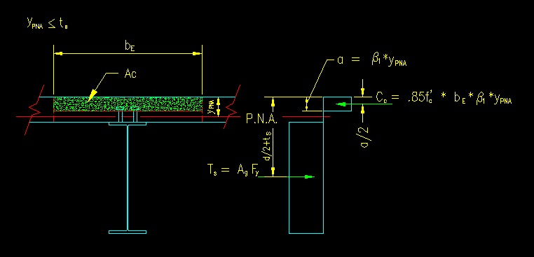
Figure 10.4.3
yPNA is in the Beam Flange
Click on image for larger view
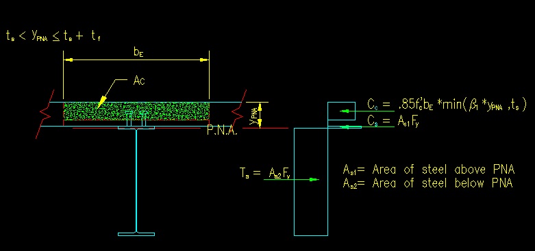
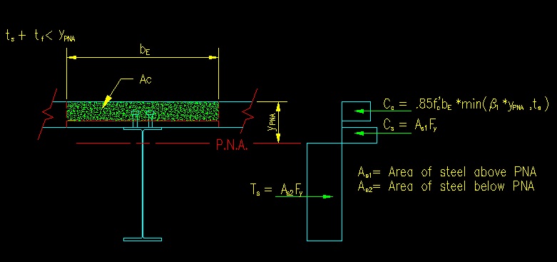
Figure 10.4.4
yPNA is in the Beam Web
Click on image for larger view
When solving the problem with a spreadsheet, expressions can be written to compute the forces for a given yPNA location. Then a solver (such as "goal seek" in Excel) can be used to find the yPNA that satisfies the equilibrium equation.
The nominal moment capacity, Mn, is then found by finding the moment that these forces create about the PNA.
Mn = Cc*(Cc dist from PNA) + Cs*(Cs dist from PNA) +Ts*(Ts dist from PNA)
If the PNA is in the slab, then Mn is the value of the couple formed by Cc and Ts since Cs is zero:
Mn = (Ts or Cc)*(distance between Ts and Cc)
More on the determination of the Area of Concrete in Compression, Ac
It is common practice to use steel decking to support the concrete slab. SCM I2.2c addresses this situation. The steel decking has ribs that give it sufficient flexural strength to support the plastic concrete until it sets. This decking may be oriented such that the ribs are either perpendicular or parallel to the beam axis, as shown in Figure 10.4.5.
Figure 10.4.5
Decking Orientation
Click on hotlinks in the image for larger
views
The area of concrete (Ac) that falls between bE and above a line parallel to the neutral axis a distance of b1ypna is the area used to compute the compressive force in the concrete. Writing an expression for Ac as a function of ypna can become a bit involved but it must be done when trying to locate the neutral axis.
One basic principle, however, is that you cannot use (in your equation) more concrete than is actually there!
Also, the resulting compressive force is located at the center of Ac. For geometries that are not rectangular, this will most likely require the computation of the center of area using principles of statics.
More information on steel decking and the various available shapes can be found on the Steel Deck Institute Website: http://www.sdi.org/.
Strength prior to the Setting of the Concrete
SCM I3.1b requires the steel beam alone to safely support, without composite action, the form work, decking, construction live loads and weight of the slab. This load case if often the one used to size the steel beam. Consideration in the strength calculation must be made for potential lack of lateral support.
If the total load is not much greater than the dead + construction loads, then the benefit of designing for composite action may be small. In such cases, to take better advantage of composite action, the beam may be "shored" (i.e., temporary supports provided to the beam) during construction until the concrete sets. Shoring temporarily shortens the beam span (and makes it a continuous beam), thus substantially reducing the moment demand on the beam during construction and before the slab gains sufficient strength to support the design loads. As a result, a smaller steel beam can be choosen and more advantage can be taken of the composite behavior.
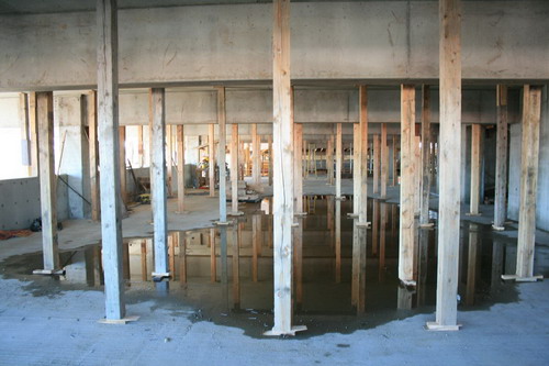
Figure 10.4.6 shows shoring in place to support a slab on a concrete structure. The shoring supports the slab until concrete gains sufficient strength to participate in resisting flexure. Similar shoring for composite beams would be placed under the beam as well as the deck.
Figure 10.4.6
Shoring in a Concrete Structure
Image by Emily Eidam, 2007
The beam is sized to support the dead + construction loads with the shoring in place as additional supports. Figure 10.4.7 contrasts the moment envelopes for the shored vs. unshored cases for beam that is shored at third points. There is a dramatic reduction in moment when the shoring is added, resulting is a smaller steel beam. Once the shoring is removed, the composite beam must have sufficient strength to meet the demand of the unshored moment diagram under all relevant loading combinations.
Figure 10.4.7
Moment Demand Comparison, Shored vs. Unshored
<<< Previous Section <<< >>> Next Section >>>