|
|
Section 10.2
Mechanics of Composite Behavior
Last Revised: 04/19/2021
As learned in mechanics, beams depend on the ability to resist longitudinal shear in order to develop strength and stiffness. The essence of composite behavior is the ability to develop this strength in the connection between the two different materials. The shear flow equation, q = VQ/I, is derived in mechanics to quantify the longitudinal shear force that must be resisted at a given distance from the beam's neutral axis.
As a mechanics review, consider the two bent beams shown in Figure 10.2.1. The beams have rectangular cross-sections of breadth, b, and laminations that are each h tall. The top beam is four laminations stacked on each but not connected to transfer shear between the laminations. The result is that each layer bends independent of its neighbors and sliding takes place between the laminations. The bending stress distribution is shown to the right.
The bending strength is proportional to the section modulus, which for this case is 4bh2/6. The stiffness is proportional to the moment of inertia which is 4bh3/12.
Figure 10.2.1
Non-Composite vs. Composite Action
Click on figure to get larger view
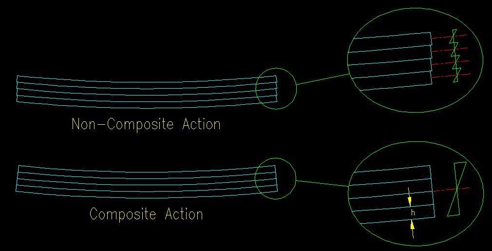
For the composite beam, the laminations are "glued" together so that the there is no sliding between the laminations. The resulting connection is a shearing connection between the laminations. In this case the section modulus and moment of inertia are b(4h)2/6 and b(4h)3/12, respectively.
Comparing the two section properties, it is apparent that the beam with composite action has four times the section modulus (which means it has four times the strength) and sixteen times the modulus of elasticity (i.e., sixteen times the bending stiffness) of the non-composite beam. That is a large increase for simply adding the ability to transfer shear between the laminations!
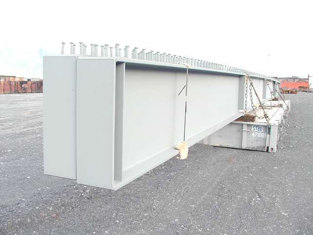
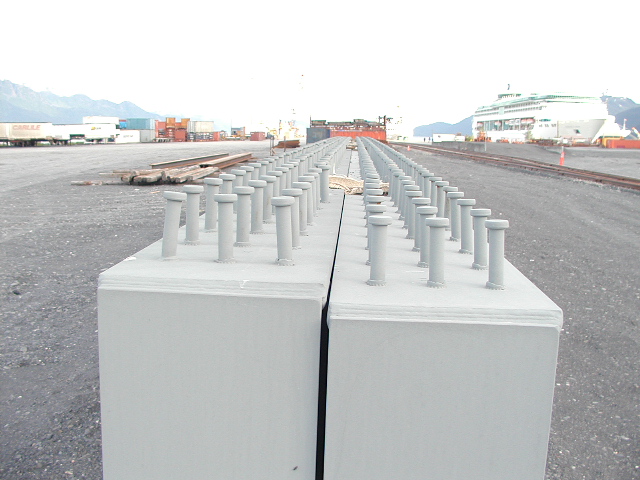
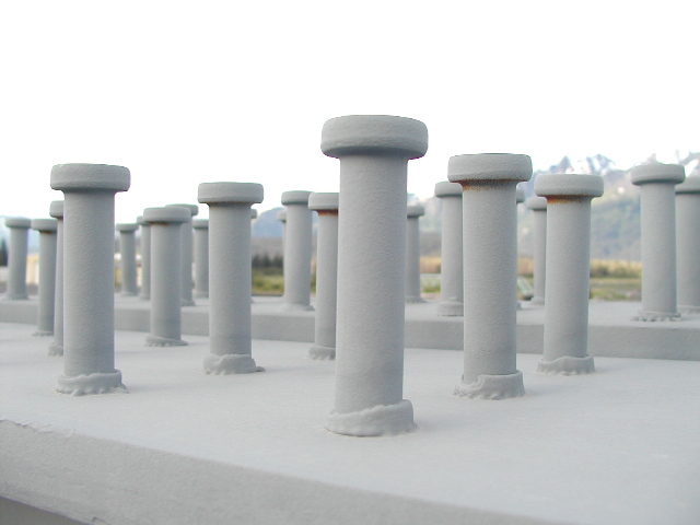
In composite steel-concrete beams, the connection between the steel beam and concrete slab is typically accomplished by welding an object to the top flange of the beam that engages the concrete directly. This is most frequently done with steel studs that are quickly and easily welded to the beam. The studs can be seen in Figure 10.2.2.
Figure 10.2.2
Typical Welded Studs
Click on thumbnails to get larger views
 |
 |
 |
Other methods of shear connection include small channels welded transverse to the beam or a spiral coil of small diameter rod welded to the top flange.
Since the concrete is generally at an extremity of the beam, it is ineffective in resisting beam shear. As a result, the presence of composite action is ignored when computing the shear capacity of the beam.
Computation of the nominal flexural strength, Mn, of the beam is computed either using a strength method or an elastic method. If the steel section's web is sufficiently compact (and all the rolled sections in the inventory are compact for Fy < 50 ksi) then strength methods are used. For plate girders (i.e., built up members) with slender webs, elastic stress distribution methods are used.
For strength methods, all the steel is assumed to be fully yielded (compression above the plastic neutral axis and tension below the plastic neutral axis) and the concrete is at its ultimate strength in the compression zone. The nominal moment capacity, Mn, is taken as the internal moment that results from the forces on the section components.
For the elastic method, elastic stresses are computed using the bending stress equation (Mc/I) on a transformed section.
This chapter focuses primarily on the strength method.
<<< Previous Section <<< >>> Next Section >>>