|
|
|
|
|
|
|
|
|
|
|
Section 8.2.1
Flexural Limit State Behavior
Last Revised: 04/19/2021
The following sections describe the behavior of concern with each of the principle flexural limit states found in SCM Chapter F. The intent of the presentation is to give a general understanding of each of the limit state behaviors. This will help you to understand the SCM limit state equations as they are presented.
The specification computes the nominal moment capacity, Mn, as the maximum moment that a member can support. This maximum moment is considered to be when the cross-section is fully yielded.
Figure 8.2.1.1 Illustrates how the stress distribution changes as moment is increased on a section.
Figure 8.2.1.1
Flexural Stress Distribution
Click on hotlinks in image for larger views
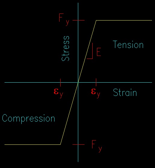
For this analysis, a simple bilinear stress-strain curve is assumed for the steel material. Stress is considered to be proportional to strain (i.e., s = Ee) until the yield stress, Fy, is reached. Figure 8.2.1.2 shows the assumed stress-strain relationship.
Figure 8.2.1.2
Simple Bilinear Stress-Strain Relationship
Click on image for larger view
Referring to Figure 8.2.1.1, as moment is applied to a cross-section, the stress in the first stage is linear until stage 2 is reached. At this point the maximum stress reaches the yield stress, which is taken as the maximum stress that the material can handle. As additional moment is applied, more of the cross-section yields (stage 3) until the section is fully yielded (stage 4). At this point, the section can support no more moment and inelastic (i.e., plastic) deformation continues to occur without the application of additional moment.
The condition where rotation can happen at a point without additional moment being applied is called a hinge condition. In other words, the fully yielded cross-section acts as a hinge with a known moment. The location of fully yielded cross-section is often times referred to as a plastic hinge and will form at the location of maximum moment on a member.
To determine the nominal moment capacity, Mn, of a section, consider a cross-section of semi-arbitrary shape (the section shown is symmetrical about it's vertical axis) shown in Figure 8.2.1.3.
Figure 8.2.1.3
Mn Determination
Click on hotlinks in image for larger views
For the case of bending without axial force, the axial equilibrium equation forces the net compressive force to equal the net tension force. Since the stresses are constant and of equal magnitude, this leads to the compression area equaling the tension area. Since the sum of the compression and tension areas equal the gross area, this leads to saying that the compression and tension areas are both equal to half the gross area. Mathematically, this is expressed as:
Compression Force = Tension Force
FyAc = FyAt
Ac = At = Ag/2
The nominal moment capacity, Mn, then equals the couple formed by the tensile and compressive forces.
Mn = Fy * (Ag/2)*(dist between centroids of the half areas)
Mn = Fy * [(Ag/2)*(dist between centroids of the half areas)]
The term within the square brackets is a section property since it is wholly dependent on cross-sectional geometry. This section property, in the SCM, is referred to as the plastic section modulus and is given the symbol "Z".
Z = (Ag/2)*(dist between centroids of the half areas)
Being a section property, this term is tabulated for all SCM shapes in the section property tables. Note that the value of Z is axis dependent. Thus, the value of Z about each principle axis is tabulated in the tables.
For sections not in the tables (for example, built up sections), the value of Z is readily determined using the definition of Z. A procedure might be:
- determine Ag
- Locate the centroidal axis
- Locate the centers of the two half areas
- Compute Z
If a section is doubly symmetric, this process can be shortened by taking the first moments of area for half of the section. Another approach would be to use the convenient SCM Table 17-27 (SCM pg 17-37) which tabulates properties of some common geometric shapes. Values of Z, like values of I, are additive if taken about the same axis, so adding values of Z for symmetric components of a cross-section is an option.
Once the plastic modulus, Z, for a section is determined the nominal moment capacity, Mn, of the section about the same axis as Z is computed by:
Mn = Fy Z
This is the plastic, or yield, strength of the member. Regardless of any other limit state, this is the absolute maximum moment that a steel member can support.
Lateral Torsional Buckling (LTB)
When a member is subjected to bending, one side of the member is in compression and wants to behave like a column while the other side is in tension. This means that the compression side is subject to flexural buckling. Since the compression side is connected to the tension side (which is not prone to buckling), it cannot buckle in the plane of loading. This leaves the lateral direction as the direction of buckling. The tension side resists the buckling, resulting in the rotated cross-section (i.e., the torsion).
A simple experiment can be used to demonstrate this behavior. Take a thin, flat bar of any rigid material (a typical "yard stick" works well) and apply end moments about the end with your hands. As you apply bending about the strong axis, the member will buckle sideways and the section will rotate so that it is no longer vertical. This is lateral torsional buckling (LTB). The experiment is illustrated in Figure 8.2.1.4.
Figure 8.2.1.4
Lateral Torsional Buckling
Click on hotlinks in image for larger views
If you bend the member about it's weak axis, this behavior is not observed. This is because the out-of-plane of bending moment of inertia of the section is larger than in-plane moment of inertia. The out-of-plane inertia then creates a stiffness out-of-plane that is larger the in-plane stiffness, thus preventing the out-of-plane buckling.
The result is that LTB is a strong axis phenomena. It need only be considered for strong axis bending.
Like all buckling, the force that will cause LTB to happen (in this case, moment) is dependent of the effective length, or slenderness, of the "column". Since the phenomena is a buckling phenomena the strength vs. slenderness curve follows the general form introduced in Figure 6.1.2 and 6.1.3. Figure 8.2.1.5 shows the general form of the curve used for LTB in the SCM. For LTB the length of the column is length of laterally unsupported compression flange. If the length is short enough, then the member can develop it's full plastic strength. For longer lengths, there is inelastic buckling, and for long laterally unbraced lengths there is elastic buckling, following a typical buckling/plastic strength curve.
Figure 8.2.1.5
Strength (Mn) vs. Slenderness (Lb) for LTB
Laterally Unbraced Lengths
It is important to be able to identify laterally unbraced lengths in flexural members. There are a few criteria that must be considered.
Two types of lateral support resist lateral torsional buckling. The first, restraining the compression side of the member from lateral motion is very common, particularly in building structures which have rigid diaphragm restraining the top of the beam. Another approach is to provide rotational restraint such that the cross-section cannot rotate, thus inhibiting the associated lateral displacement. Rotational restraint is often found in bridge structures.
If the lateral restraint is used, the lateral support must be applied to the compression flange. Bracing at mid-height or at the tension flange is not sufficient restrain buckling of the compression flange.
Second, the bracing must provide actual lateral support. Figure 8.2.1.6 shows a plan (i.e., we are looking down on it) view of a beam system with some bracing (the items running vertically in the picture). Note that there is a diagonal brace that keeps the braces on either side of it from moving laterally relative to each other. This causes these two lines to brace the beams that they are attached to. The right most run of bracing, however, is free to move laterally with respect to support on either end, so it only has the effect of causing all the beams to buckle together as shown by the red lines. The end result, in this case, is that all the beams have three laterally unbraced lengths. Each unbraced length has, potentially, it's own nominal moment capacity, Mn. These means that the moment capacity of the beam is not constant along the length of the beam. This leads to checking the flexural limit state at several different locations along some beams.
Figure 8.2.1.6
Lateral Bracing
The good news is that most bending members have full lateral support of compression flanges by roof or floor systems that they are connected to. In some cases, particularly cantilevered and continuous beams, the compression flange is on the bottom of the member so does not have any natural lateral support--the bracing must be specifically provided if it is needed. There are other cases where compression flanges are not laterally supported. This condition must be assessed on a case-by-case basis.
Dealing with Stress that Varies Along The Beam
Flexural compressive stress varies with the length of the member (it follows the moment diagram since bending stress is a function of the moment). The buckling equations assume constant compressive stress with length and are, consequently, conservative when used with only the maximum compressive stress generated by bending. This is because buckling is, to some extent, related to the strain energy stored in the compression member. With a stress that varies along the length, there is less strain energy in the whole member than a member with constant stress along its length, meaning that it is not so likely to buckle as a axially loaded member having the same maximum compressive stress along the member. To account for this behavior a means has been devised to account for variation of compressive stress along an unbraced length.
SCM F1(c) introduces a lateral-torsional buckling modification factor, Cb. Cb is a measure of the variability of the moment (and hence the compressive stress) along an unbraced length.
Take some time to review the equation for Cb found in F1(c). (See SCM page 16.1-46)
The terms MA, MB, and MC are the moments at the quarter points of the unbraced lengths.
Figure 8.2.1.7 shows a beam with three laterally unsupported lengths subjected to a uniformly distributed load and its moment diagram. The computation of Cb for each span is given in Table 8.2.1.1.
Figure 8.2.1.7
Computation of Cb
Click on image for larger view
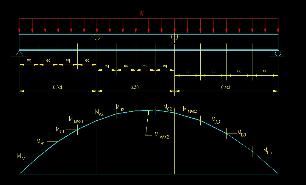
Table 8.2.1.1
Computation of Cb
| x/L | Moment/(wL^2) | Cb | ||
| Span 1 | 0.000 | 0.00000 | 1.486 | |
| MA1 | 0.075 | 0.03469 | ||
| MB1 | 0.150 | 0.06375 | ||
| MC1 | 0.225 | 0.08719 | ||
| Mmax1 | 0.300 | 0.10500 | ||
| Span 2 | MA2 | 0.375 | 0.11719 | 1.019 |
| MB2 | 0.450 | 0.12375 | ||
| Mmax2 | 0.500 | 0.12500 | ||
| MC2 | 0.525 | 0.12469 | ||
| Span 3 | Mmax3 | 0.600 | 0.12000 | 1.402 |
| MA3 | 0.700 | 0.10500 | ||
| MB3 | 0.800 | 0.08000 | ||
| MC3 | 0.900 | 0.04500 | ||
| 1.000 | 0.00000 |
Note that Cb is larger for the two laterally unbraced lengths where the moment changes the most radically. It approaches 1.0 for the laterally unbraced length which has little change in moment in its span.
Another thing to note is that changing the overall length or the intensity of the uniform load will have no effect on Cb in this case. The important thing is the relative change in the moment diagram. Look at the Cb equation and see if you can see why this is! If you expand the equations for the moment terms for most load cases, the load magnitude and span length term actually cancel out of the equation. What this means is that you need not actually compute the moments, just their relative values in order to determine Cb. Cb is a measure of the shape of the moment diagram.
Cb is used to increase the apparent nominal moment capacity of a flexural member. The specification does allow you to conservatively use Cb = 1.0 in all cases and requires it in specific instances. Check out the specification language (SCM F1, pg 16.1-46) for more details.
Flange Local Buckling (FLB) and Web Local Buckling (WLB)
Flange local buckling (FLB) and web local buckling (WLB) were, to some extent, discussed in chapter 6 on plate buckling. Unlike compression members, the limit states for flexural FLB and WLB consider all three ranges of the buckling curves. The slenderness limits to the three ranges are p and r as given in SCM Table B4.1b. The nominal moment capacity, Mn, is the moment that causes these limit states to occur. Equations are provided for different cross-section types that compute Mn for each of the ranges of the buckling in the buckling curve.
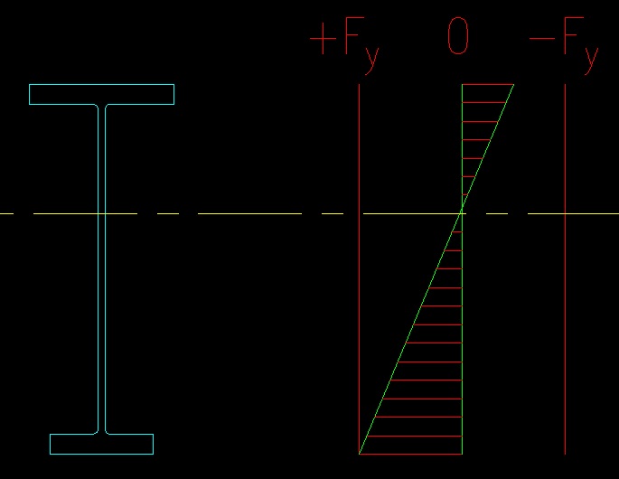
Sections that are unsymmetrical about the axis of bending and sections with slender webs may be controlled by yielding of the tension flange. For this case, the limiting moment is the one that causes stage 2 shown in Figure 8.2.1.1. This limit state will usually only become an issue for built up plate girders.
For sections with a tension flange that is further from the neutral axis than the compression flange (i.e., Sxt < Sxc), the tension flange will reach yield before the compression side as shown in Figure 8.2.1.8.
When the web is slender, it contributes little to the flexural strength of the member, so the nominal moment capacity, Mn, results when the flange yields.
When the web is not slender and can reach yield strength, then the nominal moment capacity, Mn, can be determined by the flexural yielding limit state.
Figure 8.2.1.8
Tension Flange Yielding
Click on image for larger view
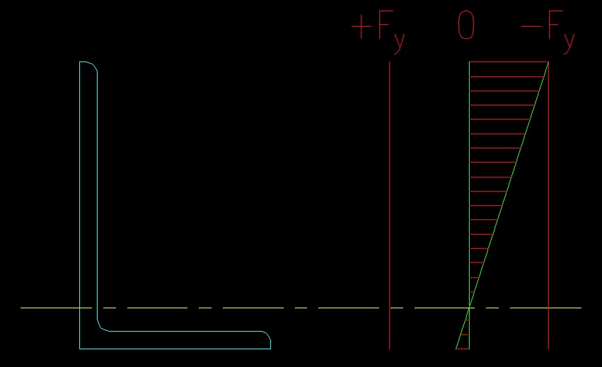
The limit state of local leg buckling (LLB) is peculiar to single angles in flexure. Similar to FLB and WLB, equations are provided for the three ranges of the buckling curve based on the width thickness ratio of the leg that is in compression.
Note that LLB applies only when the toe of the outstanding leg is in compression as shown in Figure 8.2.1.9.
Figure 8.2.1.9
LLB Condition
Click on image for larger view
<<< Previous Section <<< >>> Next Section >>>