|
|
|
|
|
|
|
|
|
|
|
Section 8.8
Example Problem 8.5
Given: A continuous beam over two spans as shown, is subjected to a uniform dead load of 2.4 kips/ft and a uniform live load of 1.8 k/ft. The beam has full lateral support. Use F7 electrodes to fillet weld the cover plate to the beam flanges. The spans are 13.5 ft and 15 ft. Use A992 steel for both the beam and flange cover plates. Figure 8.8.5.1 shows the beam geometry and loading. Use ASD.
Figure 8.8.5.1
Example 8.5 Beam Loading Diagram
Wanted: Select the lightest W section that will satisfy the flexure criteria for positive moment. Add cover plates to satisfy the flexure criteria for negative moment.
Solution: The most intensive part of this problem is in determining the moment demand envelope. Your method for doing this is irrelevant as long as you get the right values. ASD LC-2 is the controlling load combination in this problem. The solution provided in the spreadsheet utilizes moment distribution and the "influential superposition" method described in A Beginner's Guide to Structural Mechanics and Analysis.There is a large table in the spreadsheet solution that includes the moment information at 1/10th points along each span. This is normally close enough to find a maximum and minimum moment within tolerances.
The first column in the table is location along each span. The second column is location along the entire beam. The columns, LC 1 and LC 2, are the moment data that results from putting a unit load on spans 1 and 2 respectively. The column labeled "D" is the moment (using influential superposition) due to dead load only. The columns labeled Lower and Upper and the upper and lower bounds of moment demand at each point. With this data we can plot the moment envelope and see the bounds specified in the problem statement.
The peak positive moment is 78.13 ft-k. This is moment that we design the base beam for. For this problem only the strength limit states related to shear and flexure are considered. Additional analysis is required for deflection computations. These have not been considered since deflection is not likely to be a problem in continuous beams unless a very small beam is chosen.
Flexure turns out to be the controlling criteria. In this case we do not consider LTB because the beam has full lateral support so only Y and FLB are considered. The resulting best choice is a W12x22.
The W12x22 provides sufficient moment capacity at every location except for a region around the center support. The moment envelope/capacity table in the spreadsheet includes columns for the positive and negative moment capacities of the W12x22. Additional rows have been added to the table to solve for the intersection of the moment capacities with the lower bound of the moment envelope. These locations are necessary for determining where the cover plates are needed.
The next part of the problem sizes the cross section of the cover plates. There are two criteria that have an effect on the final sizes: strength and stability.
To size for strength we determine the required plastic section modulus that the plates need to provide then the required plate width is computed for several plate thicknesses. A practical size is chosen for each plate.
The width/thickness ratio for each plate is then compared against SCM Table B4.1b case 18 to ensure adequate stability. The end result of this process is that, for this problem, we have chosen to use 1/4"x3" plates attached to each flange of the beam.
Next, the connection of the plates to the beam section is needed. We are connecting these plates with fillet welds. The conservative approach taken here involves finding the maximum shear at the middle support then designing the welds for that shear as if it was that value everywhere along the beam where the plates are to be connected.
SCM J 2.2a general criteria for weld sizes say that both the maximum allowed and minimum allowed fillet weld size has a 3/16" leg size. We are constrained, then, to use a 3/16" fillet weld. This weld will be applied to both sides of each plate, so the capacity per inch of beam length equals the capacity of two 3/16" fillet welds. The capacity per inch of beam for this weld is greatly in excess that required once we compute the shear flow. The result is that we use an intermittently spaced weld as shown in the computations.
The computations show a maximum of spacing of 9.98 inches for a pair of one inch long welds. Since the plates are 3'-0" long, 9 inch spacing results in five one inch welds on each side of each plate.
The length of the plates is determined knowing the locations where the added moment capacity is required, as previously determined in the moment demand/capacity table, then adding additional length at each end to accommodate connections which develop the full capacity of the plates before being needed.
In this case, we added more than enough length for the connections to each end of the plates to arrive at an even 3'-0" dimension for the overall length of the plates. These plates are to be centered on the middle support. Added points were included in the moment demand/capacity table for the end points of the plates so that the final negative moment capacity diagram could be plotted.
Plotting the data found in the moment demand/capacity table, we get the graph shown in Figure 8.8.5.2.
Figure 8.8.5.2
Moment Demand/Capacity vs. Location
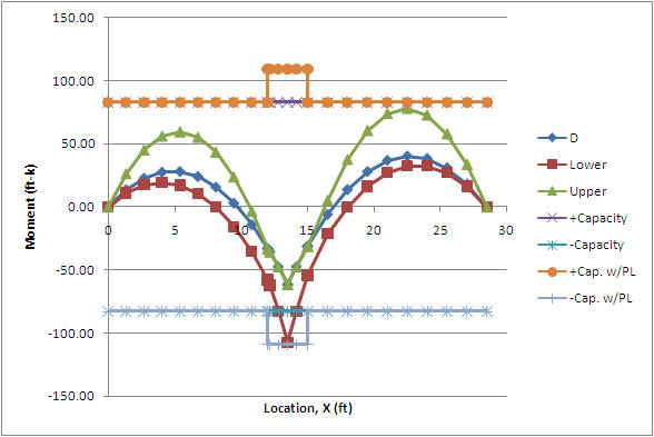
Observing Figure 8.8.5.2 we see that the moment capacity, including the cover plates, exceeds the demand in every case. The moment demand is completely inside the upper and lower bounds of the moment capacity diagrams when the capacity of the cover plates is included.
|
Figure 8.8.5.3 |
|
|
The final step in the process is to show the results on a drawing of the section. A profile of the beam showing the start and finish location would normally be necessary as well, however a note is probably sufficient here since the plates are to be centered on the support. Figure 8.8.5.3 shows the final section design.
<<< Previous Section <<< >>> Next Section >>>