|
|
Section 4.9
Example Problem 4.3
The example problems presented in this section refer to a spreadsheet solution. Click on the link below to get the file:
Chapter 4: Excel Spreadsheet Solutions
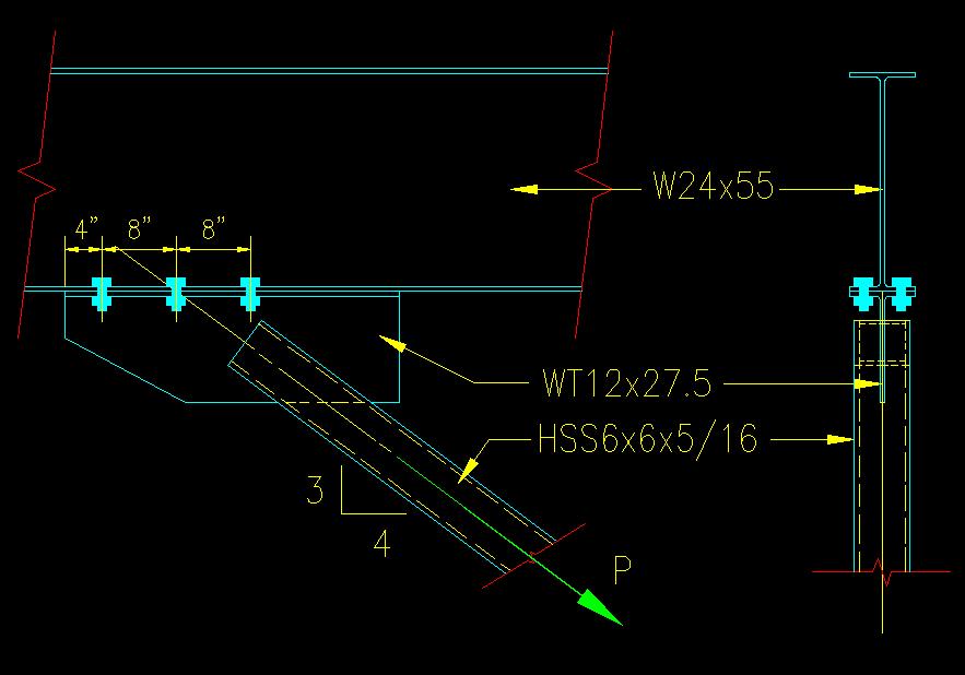
Given: A WT is bolted to a W section as part of a beam/brace connection as shown in Figure 4.9.3.1. The connection is subjected to axial tension, P. Assume that the load transferred consists only of Wind Load (100%). The W and WT are made from ASTM A992 steel. The HSS is made from ASTM A500 Gr B steel. The bolts are fully pretensioned 3/4" diameter ASTM A325-N in standard holes. The faying surfaces are class A.
Figure 4.9.3.1
Beam/Brace Connection
Click on image for larger view
Wanted: Determine the capacity of the connection based on bolt strength as specified below. Consider both LRFD and ASD. Express your results in terms of comparable service level loads.
- Determine the capacity of the connection if it is a slip critical connection.
- Determine the bearing capacity of the connection.
Solution:
Note that the line of force passes through the center of the bolt group so that there is no eccentricity. This makes the bolt force computations much easier.
The six bolts are subjected to both tension and shear. The first thing that we want to do is break P into its horizontal (shear, Pv) and vertical (tension, Pt) components:
Pv = (4/5)Pbrace Pt = (3/5)Pbrace
From the problem statement we can deduce: Ps,eq = W (the wind load).
Considering load cases, for LRFD the critical cases have Pu = 1.6 W = 1.6 Ps,eq. For ASD the critical case is Pa = W = 1.0 Ps,eq.
To find the controlling capacity in each of the given situations, the two applicable limit states (shear and tensile rupture) must be considered.
a) Slip-Critical
As an aside, this connection is very likely to be designed as slip critical because wind loads reverse direction making slip an issue.
Tension Rupture Limit State - (See SCM J3.6)
Rn = FntAb = 39.8 k/bolt
Where Fnt = 90 ksi (from Table J3.2) and Ab = .4418 in2 (area of a 3/4" diameter circle).
There are six bolts in the connection so:
Rn = FntAb = 239 k/connection
For LRFD:
Pvu = 1.6Pvs,eq = 1.6 (0.60Pbrace) < fRn = .75(239 k/connection) = 179 kips
Pbrace < 186 kips (LRFD)
For ASD:
Pva = Pvs,eq = 0.60 Pbrace < Rn/W = (239 k/connection)/2.00 = 199 kips/connection
Pbrace < 199 kips (ASD)
Slip Limit State - (See SCM J3.8 and J3.9)
rn = mDuhfTbns = 9.49 kips/per bolt
where: m = 0.30, Du = 1.13, hf = 1.00, Tb = 28 k (from SCM Table J3.1), and ns = 1 (each bolt has only 1 shear plane).
The connection has 6 bolts, so, for the connection:
Rn = (9.49 k/bolt)(6 bolts) = 57.0 kips/connection
This value needs to be reduced for the presence of tension using the factor ks found in SCM J3.9. The equation varies for LRFD and ASD.
For LRFD:
Tu = Ptu = 1.6 (0.60 Pbrace)
= 1.28 Pbrace and
Vu = Pvu = 1.6 (0.80 Pbrace)
= 0.96 Pbrace
The limit state inequality becomes
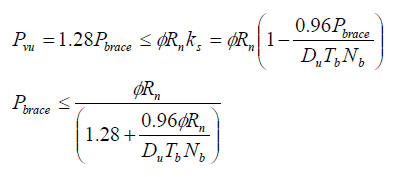
Pbrace < 36.3 kips (LRFD)
For ASD:
Ta = Pts,eq = 0.60 Pbrace and Va = Pvs,eq = 0.80 Pbrace
The limit state inequality becomes
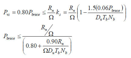
Pbrace < 38.7 kips (ASD)
b) Bearing
For the bearing-type connection, we check the shear capacity first, then the tension capacity reduced for the presence of shear.
Shear Rupture Limit State - (See SCM J3.6)
With Fnv = 54 ksi and Ab = 0.4418 in2:
rn = 23.9 k/shear plane
Rn = 143 k/connection
for LRFD:
Pvu = 1.6(.8Pbrace) < fRn = 0.75(143 k/connection) = 107.4 k/connection
Pbrace < 83.9 k/connection (LRFD)
for ASD:
Pva = 0.8Pbrace < Rn/W = (143 k/connection)/2 = 71.6 k/connection
Pbrace < 89.5 k/connection (ASD)
Tension Rupture Limit State - (See SCM J3.6 and J3.7)
The SCM equations are set up for analysis (i.e. where you know what the applied load is). Since we don't know what the applied force is (we are solving for that), we will need to do a bit of algebra.
First, we will compute the capacity without the reduction. This is the upper limit on capacity. If, after applying the reduction formulas, the value turns out to be larger than the capacity without the reduction, we will use the lower value. This approach is consistent with the limits given in J3.7.
With Fnt = 90 ksi and Ab = 0.4418 in2:
rn = 39.8 k/bolt
Rn = 239 k/connection
for LRFD:
Ptu = 1.6(.6Pbrace) < fRn = 0.75(239 k/connection) = 179 k/connection
Pbrace < 186 k/connection (LRFD)
for ASD:
Pta = 0.6Pbrace < Rn/W = (239 k/connection)/2 = 119 k/connection
Pbrace < 199 k/connection (ASD)
Applying the reduction equations for F'nt in SCM J3.7:
For LRFD:
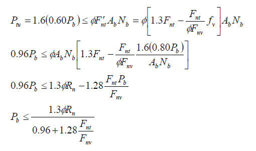
Pbrace < 69.2 k/connection (LRFD)
for ASD:
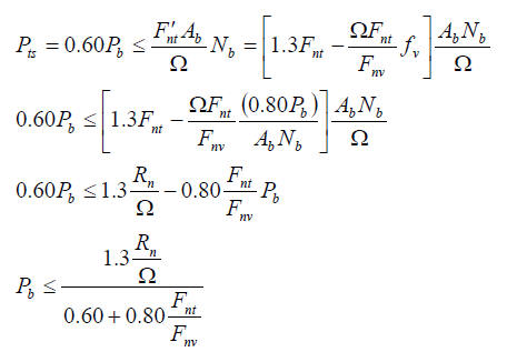
Pbrace < 73.8 k/connection (ASD)
Since the reduced values are less than the unreduced values, those are the ones that control.
Solution Summary:
| Allowable Brace Force (at comparable service levels) | ||||||
| Part (a) Slip Critical | ||||||
| LRFD | ASD | |||||
| (k) | (k) | |||||
| Slip | 36.3 | 38.7 | <--- Controls | |||
| Tensile Rupture | 186 | 199 | ||||
| Controlling Limit | 36.3 | 38.7 | ||||
| Part (b) Bearing | ||||||
| LRFD | ASD | |||||
| (k) | (k) | |||||
| Shear Rupture | 83.9 | 89.5 | ||||
| Tensile Rupture | 69.2 | 73.8 | <--- Controls | |||
| Controlling Limit | 69.2 | 73.8 | ||||