Example #4
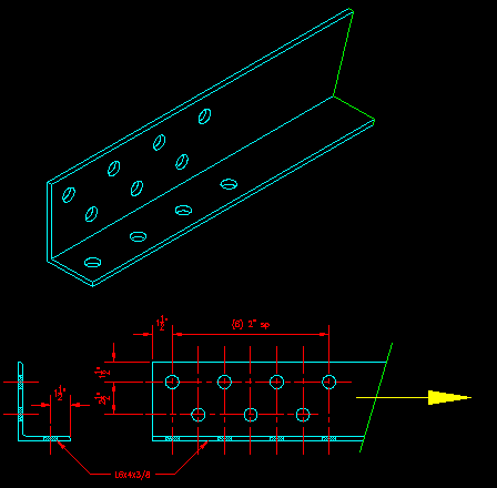
A L6x4x3/8 tension member is attached on both legs with 7/8" diameter bolts. A drawing of the member's end is shown in Figure FP-4a.

Figure FP-4a
End of a Tension Angle
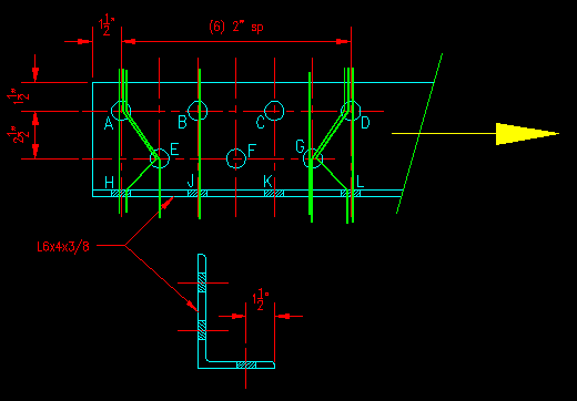
Figure FP-4b shows some possible failure paths with the green lines. Note that they all start and end perpendicular to the direction of force.

Figure FP-4b
Possible Failure Paths
Shown are eight possible failure paths. You should be able to come up with a few more. So the question is, which or the indicated paths are valid?
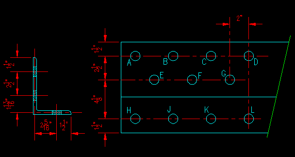
When computing path length for the various path's, the lengths are measured along the center of the leg thickness as shown in Figure FP-4c. One way to deal with this is to "layout flat" the angle as shown in the figure.

Figure FP-4c
Equivalent Plate
The width dimension for the equivalent plate equals the sum of the leg lengths less a thickness:
Equivalent Plate Width = 6" + 4" - .375" = 9.625"
Note that you will get slightly different results from this approach than from method of deducting areas from the recorded Ag for the angle. This because this method does not account for fillets at the ends of the legs and at the plate intersection. The difference is not significant.
Click the link for each path to see if it is valid or not. Try to figure out which is valid before checking! For the valid paths, you will be asked to compute the failure path length and the associated net area of the plate.