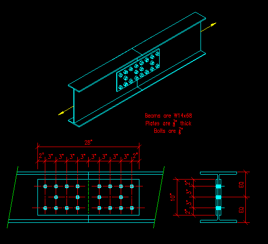
Example #2
In this example we will connect two W14x68s with a pair of 3/8" thick splice plates as shown in Figure FP-2a.
Figure FP-2a
Tension Splice for Two W Sections
This connection consists of four members: two W sections and two plates. The two W sections are identical and the two splice plates are identical, so we only need consider one W section and one plate.
Figure FP-2b show a FBD for the end of a W section with several possible failure paths. You can probably identify more possible paths, but the set shown does include all VALID paths.
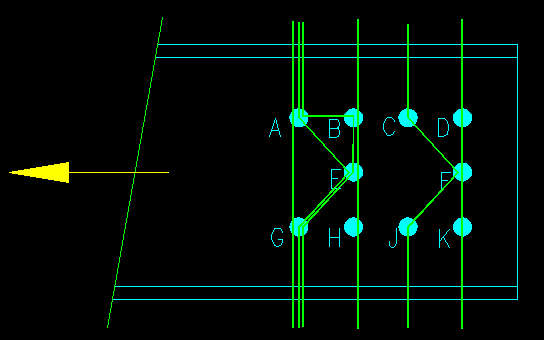
Figure FP-2b
FBD of W Section End
Click the link for each path to see if it is valid or not. Try to figure out which is valid before checking! For the valid paths, you will be asked to identify the failure path length and the associated net area of the plate.
Let's now look at the splice plate.
Figure FP-2c show an FBD of the end of one of the splice plates with the same failure paths considered for the W section. Again there are more potential failure paths than shown, but the given set includes the valid failure path(s).
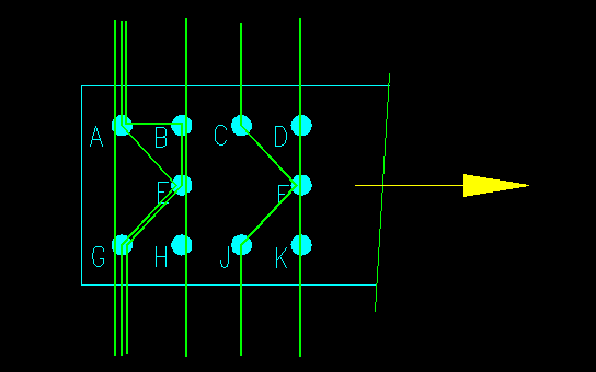
Figure FP-2c
FBD of the Splice Plate End
Click the link for each path to see if it is valid or not. Try to figure out which is valid before checking! For the valid paths, you will be asked to compute the failure path length and the associated net area of the plate.