|
|
|
|
|
|
|
|
|
|
|
Section 8.2.5
Compression Flange Local Buckling Limit State
Last Revised: 06/16/2011
Local buckling of the compression flange (FLB) occurs when the width/thickness ratio of the plate elements is high. The general concept was discussed in some detail in the notes on plate buckling. The specific application to flexural members is found in SCM Chapter F. Using SCM Table User Note F1.1 as a reference, one or the other of FLB appears in SCM F3, F4, F5, F6, F7, and F9.
Note that there are a limited number of rolled sections which have problems with FLB and WLB. The SCM user notes in F2, F3, and F6 point out the sections that are likely to have problems with WLB and FLB for a given range of Fy. As Fy increases, more sections become non-compact and slender, thus invoking WLB and FLB limits on strength.
The Limit State
The basic limit state follows the standard form. The statement of the limit states and the associated reduction factor and factor of safety are given here:
| LRFD | ASD |
| Mu < fbMn | Ma < Mn/Wb |
| Req'd Mn = Mu/fb < Mn | Req'd Mn = Mu Wb < Mn |
| Mu / (fbMn) < 1.00 | Ma / (Mn/Wb) < 1.00 |
| fb = 0.90 | Wb = 1.67 |
The values of Mu and Ma are the LRFD and ASD factored loads, respectively, applied to the flexural member.
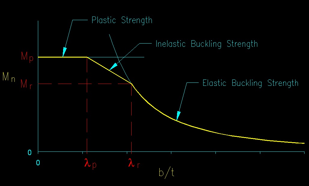
In this case Mn is the nominal FLB limited flexural strength of the member. Since this is a buckling phenomena, limits need to be found for the three strength regions: plastic, inelastic buckling, and elastic buckling as shown in Figure 8.2.1.5.
The General Form
The general form of the FLB limit state follows the typical buckling curve. The slenderness parameter used is width/thickness ratio (b/t) as specified in SCM B4.
The limits of the buckling regions are specified by the terms lp (the limit of the plastic region) and lr (the limit of the inelastic buckling region). Hence:
- if l = b/t < lp then the plastic strength, Mp, controls and FLB does not occur
- if lp < l = b/t < lr then inelastic FLB occurs
- if lr < l = b/t then elastic FLB occurs
Figure 8.2.5.1 illustrates the concept.
Figure 8.2.5.1
General FLB Strength
Click on image for larger view
Both lp and lr are computed using the appropriate cases and equations from SCM Table B4.1.
Mp
- SCM F4: Mp = RpcMyc = RpcFySxc, as found in SCM F4.1.
- Rpc is computed using SCM Eq. F4-9.
- SCM F5: Stresses are used instead of moments. Fy takes the place of Mp (extracted from SCM equation F5-3) in the general form of the equation for the inelastic buckling region. Mp becomes RpgFySxc (SCM equation F5-1)
- SCM F6: Mpy = min (FyZy, 1.6FySy)
- SCM F7: Mpx = FyZx; Mpy = FyZy
Mr
The moment at the interface of the elastic and inelastic ranges, Mr, is found embedded in the linear interpolation function found in several of the specification sections used to compute the strength in the inelastic buckling range.
- SCM F3: Mr = 0.7FySx (extracted from SCM equation F3-1)
- SCM F4: Mr = FLSxc (extracted from SCM equation F4-12)
- SCM F5: Stress is used instead of moments. Fr takes the place of Mr
(Fr =
0.3Fy, extracted from SCM equation F5-8) in the general form of the
equation for the inelastic buckling region.
- While not used in the equations of SCM F5, Mr = RpgFrSxc.
- SCM F6: Mr = 0.7FySy (extracted from SCM equation F6-2)
- SCM F7 & F9: The general form of the inelastic buckling equation is not used (though the ones used are still linear with b/t) so computing Mr is not useful.
Plastic Range
As noted above, when l < lp FLB does not happen. Consequently in the plastic range, Mn equals Mp.
In-elastic Buckling Range
- SCM F3, F4, & F6: A linear interpolating function is used to compute Mn in the in-elastic buckling range. This resulting value is compared with Mp to find the final Mn.
The equation can be written as:
Mn = min [(Mp - (Mp - Mr)*(l - lp)/(lr - lp)), Mp]
- SCM F5: A similar linear interpolation function is used:
Mn = FcrRpgSxc = min [(Fy - 0.3Fy (l - lp)/(lr - lp)), Fy] RpgSxc
- SCM F7:
For SCM F9:
Elastic Buckling Range
The nominal moment capacity, Mn, in the elastic range is found by computing the elastic moment that creates the critical buckling stress, Fcr, in the compression flange.
Mn = min[FcrSxc, Mp]
A modified Euler type function is used to the compute the critical buckling stress, Fcr.
- SCM F3, F4, & F5: Mn is computed with the equation:
- SCM F7 & F9:
Download a summary of FLB equations here.
Sample Spreadsheet CalculationThe following spreadsheet example computes the major axis flexural capacity, Mnx, including FLB effects, for a typical W section. The input values are in the grey shaded cells and the result in the yellow highlighted cell.
| Flange Local Buckling | ||||||
| SCM F4 | ||||||
| Section | W12x65 | |||||
| Steel: | A992 | |||||
| Fy | 50 | ksi | ||||
| FL | 50 | ksi (SCM F4.2(ii)) | ||||
| lpf | 9.15 | SCM Table B4.1, case 1 | ||||
| lpw | 90.6 | SCM Table B4.1, case 9 | ||||
| lrw | 137.3 | SCM Table B4.1, case 9 | ||||
| Tabulated Section Properties | Computed Section Quantities | |||||
| h/tw | 24.9 | kc | 0.760 | |||
| bf/2tf | 9.92 | |||||
| Sx | 87.9 | in^3 | ||||
| Zx | 96.8 | in^3 | ||||
| Computations | ||||||
| l | 9.92 | |||||
| lp | 9.2 | |||||
| lr | 24.1 | |||||
| Mp | 4840 | in-k (SCM Eq. F4-9) | ||||
| Myc | 4395 | in-k (SCM Eq. F4-4) | ||||
| Rpc | 1.10 | (SCM eq. F4-9) | ||||
| Mn | 4817 | in-k | ||||
| Mn | 401.4 | ft-k | <---- Answer | |||
<<< Previous Section <<< >>> Next Section >>>