|
|
Section 4.9
Example Problem 4.5
The example problems presented in this section refer to a spreadsheet solution. Click on the link below to get the file:
Chapter 4: Excel Spreadsheet Solutions
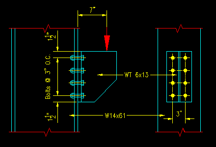
Given: A bracket is connected to a column flange as shown in Figure 4.9.5.1. Assume that the applied load is 50% D and 50% L. The bolts are pretensioned 7/8" diameter A325-N bolts. The faying surface is class A.
Figure 4.9.5.1
Out-of-Plane Eccentricity
Click on image for larger view
Wanted: Determine the capacity of the connection based on bolt strength as specified below. Consider both LRFD and ASD. Express your results in terms of comparable service level loads.
- Determine the bearing capacity of the connection using the SCM Case I method.
- Determine the bearing capacity of the connection using the SCM Case II method.
Solution:
The problem has been solved in the spreadsheet provided for this problem. The following explanation is intended to help you understand the spreadsheet computation.
The composite load factors will be needed later in the problem to convert values for Pu and Pa to comparable Ps,eq values so they have been computed first.
Shear Capacity
For both of these problems, the shear limit states are identical so let's look at that first:
The design inequality for the shear case is:
LRFD: ruv < frnv ASD: rav < rnv / W
Where:
rnv = FnvAb
ruv = Pu / (nbAb)
rav = Pa / (nbAb)
Substituting these values into the limit state equations above, it is fairly simple task to solve for Pa and Pu. The resulting values are converted to Ps,eq values for comparison. Note that the computation for both Case I and Case II are identical for the shear limit state in this case. This is because the shear capacity is not modified for the presence of tension for bearing type (-N and -X) bolted connections.
a) Case I Tension Capacity
Again, for this case we need to start with the design inequalities:
LRFD: rut < frnt ASD: rat < rnt / W
Where:
rnt = F'ntAb
rut = Pu e c Ab/ Ix
rat = Pa e c Ab/ Ix
c = maximum distance from the N.A. to the center of a bolt.
Determining the section properties Ix and c are explained in the SCM on pages 7-10 and 7-11. The approach is to locate the neutral axis by finding where the areas above and below the axis are equal. In this case, the bolts in the compression zone are ignored, which makes the computation a bit iterative. Once the N.A. is located then the moment of inertia, Ix, can be computed as long as the maximum value of c.
The equations for F'nt can be found in the SCM as equations J3-3.
After making substitutions, the resulting design inequalities become:
LRFD: Pu e c Ab/ Ix < f min[1.3Fnt - (Pu/(nbAb))(Fnt/(fFnv)) , Fnt] Ab
ASD: Pa e c Ab/ Ix < min[1.3Fnt - (Pu/(nbAb))(WFnt/Fnv) , Fnt] Ab / W
These equations can then be solved for Pu and Pa, which in turn can be converted to comparable Ps,eq. The results are summarized in the results table.
Case II Tension Capacity
The approach is the same except the values for rut and rat are computed differently.
This case is simpler in that there is no need to compute Ix or c. The formulas for this method are presented in the SCM on page 7-12.
rut = Pu e / (n' dm)
rat = Pa e / (n' dm)
After making substitutions, the resulting design inequalities become:
LRFD: Pu e / (n' dm) < f min[1.3Fnt - (Pu/(nbAb))(Fnt/(fFnv)) , Fnt] Ab
ASD: Pa e / (n' dm) < min[1.3Fnt - (Pu/(nbAb))(WFnt/Fnv) , Fnt] Ab / W
Again, these equations can then be solved for Pu and Pa, which in turn can be converted to comparable Ps,eq. The results are summarized below.
Solution Summary:
| LRFD | ASD | |||||
| (kips) | (kips) | |||||
| a | Case I | |||||
| Shear limit | 123.70 | 115.45 | ||||
| Tension limit | 77.35 | 48.75 | ||||
| Controlling Value | 77.35 | 48.75 | <---- Answer (a) | |||
| b | Case II | |||||
| Shear limit | 123.70 | 115.45 | ||||
| Tension limit | 62.38 | 46.26 | ||||
| Controlling Value | 62.38 | 46.26 | <---- Answer (b) | |||
